Table of Contents
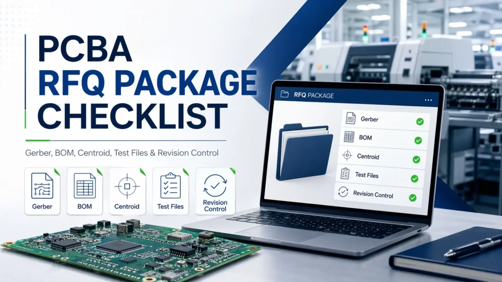
PCBA RFQ Package Checklist: Gerber, BOM, Centroid, Test Files & Revision Control
A PCBA quote is not calculated from board size or component count alone. A reliable quotation depends on the complete manufacturing picture: PCB fabrication data, component sourcing risk, placement accuracy, assembly requirements, testing scope, programming needs, production quantity, lead time, and revision control.
For engineers and purchasing teams, a clean RFQ package can shorten review time, reduce engineering questions, and make supplier quotations easier to compare. More importantly, it helps prevent the common problem behind many delayed PCBA projects: the supplier is forced to quote based on assumptions because key information is missing or inconsistent.
This guide explains what to include in a professional PCBA RFQ package, how each file affects quotation accuracy, and how to control revisions before prototype, pilot run, or mass production.
Why a Complete PCBA RFQ Package Matters Before Quoting
A PCBA RFQ is not just a request for price. It is the starting point for engineering review, material sourcing, process planning, inspection strategy, testing preparation, and production scheduling.
When the RFQ package is complete, the manufacturer can review the project with fewer assumptions. When it is incomplete, the quotation may still be possible, but it is usually less stable.
A quote is only as accurate as the files behind it
A PCBA manufacturer normally evaluates several areas before quoting:
| Review Area | What the Supplier Needs to Check |
|---|---|
| PCB fabrication complexity | Board layers, material, copper weight, drill files, board outline, surface finish, impedance needs, special structures |
| Component sourcing | BOM accuracy, MPNs, approved alternates, long-lead items, obsolete parts, customer-supplied parts |
| Assembly process | SMT/THT mix, fine-pitch parts, BGA/QFN packages, double-sided placement, manual assembly steps |
| Placement data | Centroid accuracy, X/Y coordinates, rotation, top/bottom side, reference designator matching |
| Testing and programming | ICT, flying probe, FCT, firmware, programming method, test fixture, pass/fail criteria |
| Commercial requirements | Quantity, quote breaks, lead time, shipping destination, packaging, sourcing responsibility |
| Revision control | Whether Gerber, BOM, centroid, drawings, firmware, and test files belong to the same build revision |
If any of these areas are unclear, the supplier must either ask follow-up questions or quote with assumptions. Both can slow down the project.
Incomplete RFQs create hidden assumptions
An incomplete RFQ does not always stop the quotation process. It often creates hidden assumptions instead.
For example, if the BOM does not include manufacturer part numbers, the supplier may not know which exact components to quote. If the test requirement only says “functional test required,” the supplier cannot estimate fixture cost, test software work, or operator time accurately. If Gerber, BOM, and centroid files come from different revisions, the quotation may be based on a file set that cannot be built safely.
| Missing or Unclear Information | Hidden Assumption It May Create | Possible Result |
|---|---|---|
| BOM without MPNs | Supplier assumes generic or available alternatives | Price change, performance risk, sourcing delay |
| No centroid file | Supplier estimates SMT programming and placement effort | Inaccurate assembly cost |
| No test procedure | Supplier assumes basic inspection or power-on check only | Later NRE, fixture, or test cost increase |
| No firmware/programming notes | Programming is treated as out of scope | Production delay or added service cost |
| No special process notes | Coating, potting, cleaning, staking, or labeling is not quoted | Additional cost after engineering review |
| No revision control | Supplier assumes files belong to the same build | Risk of quoting or building the wrong version |
A good RFQ package moves these risks to the front of the project, where they are easier and cheaper to clarify.
A clean RFQ package helps buyers compare suppliers fairly
For purchasing teams, RFQs are often sent to multiple suppliers. Fair comparison only works when every supplier quotes against the same technical and commercial baseline.
That means using:
- The same Gerber or ODB++ package
- The same BOM revision
- The same centroid file
- The same test scope
- The same quantity breaks
- The same lead time target
- The same turnkey, consigned, or partial-turnkey responsibility
- The same packaging and shipping assumptions
If one supplier quotes with functional testing included and another quotes without it, the lower price may not actually be lower. If one supplier assumes all components are turnkey while another assumes customer-supplied parts, the two quotations are not comparable.
A controlled RFQ package gives every supplier the same starting point.
Quick Answer: What Should Be Included in a PCBA RFQ Package?
Minimum files for a basic PCBA quote
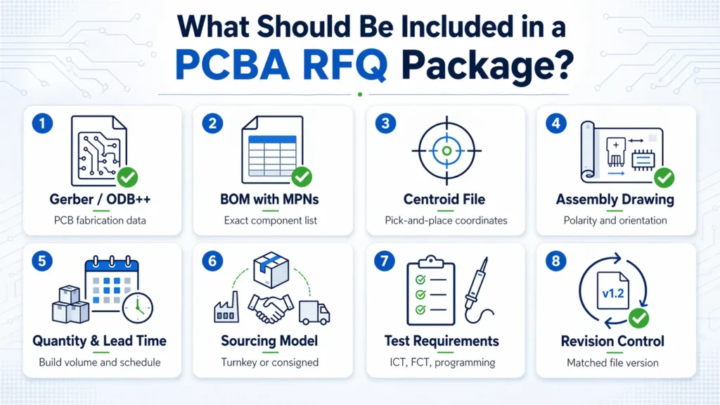
For most PCB assembly quotations, prepare the following:
| File or Information | What It Should Include | Why It Matters |
|---|---|---|
| Gerber or ODB++ files | Copper layers, solder mask, silkscreen, paste layer, drill files, board outline | Defines PCB fabrication and assembly preparation |
| BOM with MPNs | Reference designators, quantities, manufacturer part numbers, package, description | Supports sourcing, cost review, and material risk checking |
| Centroid / Pick-and-Place file | Ref Des, X/Y coordinates, rotation, top/bottom side | Supports SMT programming and placement review |
| Assembly drawing | Component position, polarity, pin 1, connector orientation, DNP notes | Reduces orientation and manual assembly errors |
| Quantity | Prototype, pilot run, mass production, quote breaks if available | Affects material planning and unit price |
| Target lead time | Expected delivery schedule and urgency | Affects sourcing and production planning |
| Sourcing model | Turnkey, consigned, or partial-turnkey | Defines who is responsible for materials |
| Test requirements | Inspection, ICT, FCT, programming, or basic functional check | Affects NRE, fixture, labor, and lead time |
These files are usually enough for a meaningful initial review. For complex builds, they are only the starting point.
Recommended files for a more accurate quote
| Recommended File | Why It Helps |
|---|---|
| Schematic | Helps engineers understand circuit function, test planning, and troubleshooting needs |
| Fabrication drawing | Clarifies board thickness, copper weight, stack-up, tolerance, impedance, and surface finish |
| Panelization drawing | Helps review production handling, tooling, and assembly efficiency |
| 3D / STEP file | Helps check mechanical fit, connector alignment, height limits, and fixture planning |
| IPC class or acceptance requirement | Defines the expected quality and inspection standard |
| Programming instructions | Clarifies firmware loading method, connector, tool, and security requirements |
| Packaging and labeling requirements | Prevents assumptions about ESD bags, trays, cartons, barcodes, serial numbers, or shipment format |
These details help the supplier quote closer to the real production condition instead of relying on default assumptions.
Project-specific files for complex builds
| Project Requirement | Useful RFQ Information |
|---|---|
| ICT | Test points, netlist, fixture requirement, coverage expectation |
| Flying probe | Netlist, test access constraints, prototype quantity |
| FCT | Test procedure, pass/fail limits, cables, interface board, software, operator steps |
| Firmware programming | HEX/BIN file, programming method, connector, verification method |
| Calibration | Required equipment, tolerance range, calibration steps, record format |
| Conformal coating | Coating area, keep-out zones, material preference, thickness requirement |
| Potting / staking / glue | Application area, material, curing requirement |
| Serialization | Serial number rule, barcode format, data logging requirement |
| Traceability | Batch record, component lot tracking, production data requirement |
If these requirements exist but are not included in the RFQ, they may appear later as cost, schedule, or quality-control changes.
Gerber or ODB++ Files: What the Manufacturer Checks
Required PCB fabrication layers
| Required Data | Purpose |
|---|---|
| Copper layers | Define electrical routing and power/ground planes |
| Solder mask layers | Define exposed pads and mask openings |
| Silkscreen layers | Provide reference marks, polarity marks, and assembly guidance |
| Paste layers | Support SMT stencil preparation |
| NC drill files | Define plated and non-plated holes |
| Board outline | Defines final PCB shape and routing path |
| Fabrication notes | Clarify surface finish, material, copper weight, tolerance, or special requirements |
| Stack-up information | Important for multilayer boards, impedance control, and signal integrity |
The paste layer is especially important for SMT assembly. The board outline is also critical because it affects panelization, tooling, handling, and routing.
Common Gerber issues that delay RFQ review
| Gerber Issue | Why It Causes Problems |
|---|---|
| Missing paste layer | Stencil review and SMT preparation cannot be completed clearly |
| Missing or unclear board outline | Board size, routing, panelization, and tooling may be assumed incorrectly |
| Missing drill file | PCB fabrication cost and process review cannot be completed |
| Drill data does not match layers | CAM review may stop until files are corrected |
| Silkscreen over pads | May affect soldering or inspection readability |
| No fabrication notes | Material, finish, copper weight, or tolerance may be assumed |
| Old Gerber revision | May not match the latest BOM, centroid, or assembly drawing |
Before sending files, confirm that the Gerber or ODB++ package belongs to the same revision as the BOM, centroid file, assembly drawing, and test files.
Gerber vs ODB++: which is better for RFQ review?
Gerber is widely accepted and suitable for most standard PCB and PCBA quotations. ODB++ can provide richer manufacturing data in a more integrated structure, which may help reduce ambiguity during engineering review.
For many projects, a complete and current Gerber package is enough. For dense, complex, or high-reliability boards, ODB++ can make the review process more efficient.
The file format matters less than the quality of the data. The best file package is complete, readable, current, and consistent with the rest of the RFQ.
BOM Checklist: What a Manufacturer Needs for Sourcing and Costing
The BOM is one of the most important files in a PCBA RFQ package. It drives component sourcing, cost calculation, lead time review, alternate part planning, and material risk assessment.
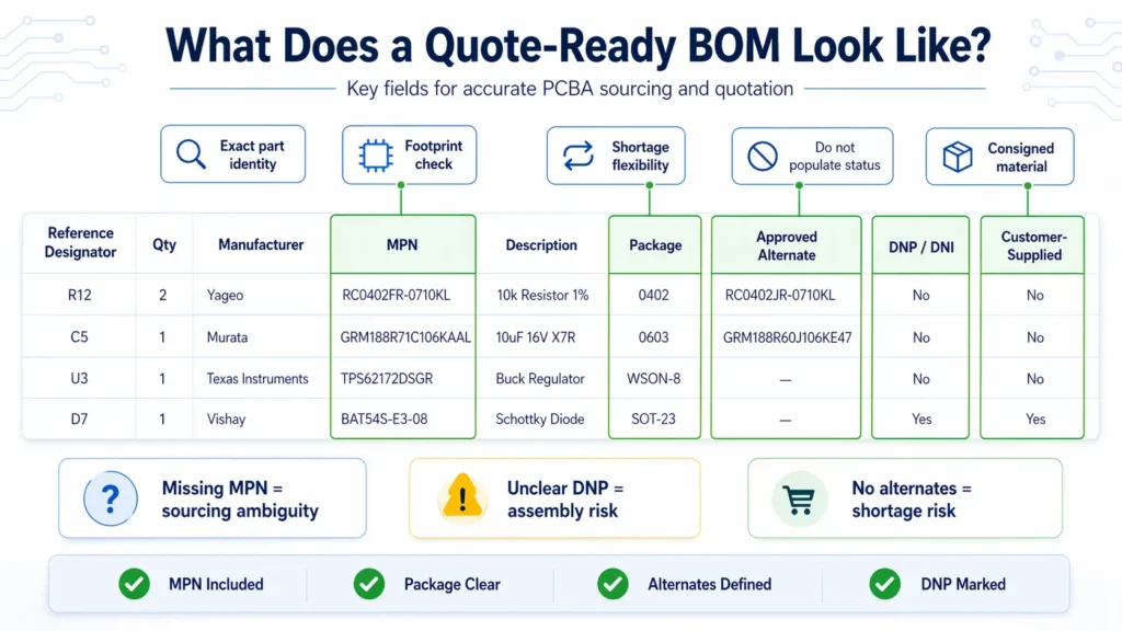
A BOM that only lists generic values is not enough for a controlled quote. “10k resistor” or “10µF capacitor” can describe many parts with different packages, tolerances, voltage ratings, temperature characteristics, and supply conditions.
Essential BOM columns
| BOM Field | Why It Matters |
|---|---|
| Reference Designator | Links each part to a specific board location, such as R1, C5, or U3 |
| Quantity Per Board | Defines the exact material demand for each PCBA |
| Manufacturer Part Number | Identifies the exact component to source and quote |
| Manufacturer Name | Helps avoid ambiguity when similar part numbers exist |
| Description / Value | Supports engineering review and purchasing verification |
| Package / Footprint | Helps compare BOM data with PCB pads and centroid data |
| Approved Alternates | Gives purchasing flexibility when the primary part has shortage or long lead time |
| DNI / DNP Notes | Prevents parts from being quoted or installed when they should not be populated |
| Customer-Supplied Parts | Clarifies consigned material responsibility |
| Critical Parts | Identifies parts that cannot be substituted without approval |
| Sourcing Notes | Clarifies AVL, authorized channel, lifecycle, or brand restrictions |
The most important field is the manufacturer part number. Without it, sourcing becomes interpretation rather than verification.
BOM mistakes that cause quote changes
| BOM Problem | What Can Happen |
|---|---|
| Missing MPN | Supplier may quote a generic or lower-cost part that does not match the design intent |
| Invalid or incomplete part number | Purchasing must stop for clarification |
| Package mismatch | PCB footprint may not match the physical part |
| Wrong quantity per board | Material cost and availability may be calculated incorrectly |
| Reference designators missing or inconsistent | BOM cannot be matched cleanly to centroid or assembly drawings |
| DNP/DNI parts not marked clearly | Parts may be purchased or assembled by mistake |
| No approved alternates | Shortage response becomes slower and more expensive |
| Customer-supplied parts not separated | Turnkey and consigned responsibilities become unclear |
| BOM revision does not match Gerber | Supplier may quote parts for the wrong board version |
A strong BOM reduces sourcing uncertainty before the quote is issued. It also gives the supplier a better chance to flag long-lead, obsolete, high-risk, or unclear components early.
Turnkey vs consigned BOM requirements
| Sourcing Model | BOM Requirement |
|---|---|
| Turnkey | The BOM must include complete MPNs, manufacturers, package data, approved alternates, and sourcing restrictions because the supplier is responsible for procurement |
| Consigned | The BOM must match the customer-supplied materials exactly, including reference designators, quantities, and package descriptions |
| Partial Turnkey | The BOM should clearly separate supplier-sourced parts from customer-supplied parts |
For partial-turnkey projects, it is helpful to add a dedicated BOM column such as:
- Supplier Source
- Customer Supplied
- Do Not Populate
- Approved Alternate Allowed
- Critical / No Substitute
- Programmed Part
- Moisture-Sensitive Part
This prevents confusion during quoting, material preparation, and production scheduling.
Centroid / Pick-and-Place File: Why It Must Match the BOM
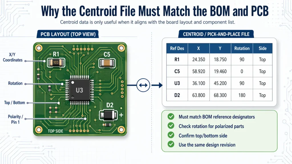
The centroid file, also called the pick-and-place file or XY file, gives the assembly equipment the information needed to place SMT components on the PCB.
It must not be treated as a separate file. It should be checked against the BOM, Gerber, and assembly drawing before sending the RFQ.
What a centroid file should include
| Centroid Field | Purpose |
|---|---|
| Reference Designator | Connects each placement point to the BOM |
| X Coordinate | Defines horizontal placement position |
| Y Coordinate | Defines vertical placement position |
| Rotation | Defines component orientation |
| Top / Bottom Side | Identifies which PCB side the component is placed on |
| Package / Footprint | Helps verify placement data against BOM and PCB design |
| Part Value or MPN | Useful for additional cross-checking |
Coordinate units should be clear and consistent. Rotation data should be reviewed carefully for polarized components, ICs, connectors, and double-sided assemblies.
Why BOM and centroid mismatches matter
BOM and centroid mismatches can delay quotation and create production risk.
Examples include:
- The BOM lists R1–R10, but the centroid file does not include R8.
- The BOM marks a component as DNP, but the centroid file still includes placement data.
- The centroid file contains a reference designator not found in the BOM.
- A diode, capacitor, IC, or connector has unclear rotation.
- The centroid file was exported from an older PCB revision.
- Top and bottom side information is missing or inconsistent.
These problems can affect SMT programming, first article inspection, test results, and production yield.
When centroid data may need engineering correction
Centroid files are usually exported from EDA software, but they are not always production-ready without review.
Engineering correction may be needed when:
- Different design tools use different rotation conventions
- Bottom-side components require mirrored handling
- Non-standard components have unusual pick centers
- Polarized components need additional orientation confirmation
- Panelized boards require adjusted coordinates
- Custom footprints do not match the physical component body
For quote review, the supplier may not need to correct every detail immediately. But visible inconsistency between BOM, centroid, and assembly drawings should be clarified before the quotation becomes a production plan.
Assembly Drawings and Special Instructions
An assembly drawing provides visual manufacturing guidance. It helps the supplier understand component position, orientation, polarity, manual assembly steps, and inspection requirements.
A good assembly drawing is not just a screenshot of the PCB layout. It should be clear enough for engineering, SMT programming, hand assembly, inspection, and repair teams to use.
What should be shown in an assembly drawing
| Drawing Element | Why It Matters |
|---|---|
| Component outlines | Helps verify physical placement |
| Reference designators | Links the drawing to BOM and centroid data |
| Polarity marks | Prevents reverse placement of diodes, capacitors, LEDs, and ICs |
| Pin 1 indicators | Critical for ICs, connectors, and modules |
| Connector orientation | Prevents mechanical fit and cable connection issues |
| Top and bottom views | Required for double-sided assemblies |
| DNP/DNI markings | Shows which positions should not be installed |
| Mechanical keep-out zones | Helps avoid interference with housing, screws, heat sinks, or test probes |
| Hand-soldering notes | Clarifies manual or post-reflow operations |
| Labeling notes | Defines barcode, serial number, or product label position |
For boards with both SMT and through-hole components, the drawing should also make the assembly sequence clear enough to support process planning.
Special process notes that affect quote accuracy
Many quotation changes come from special processes that were not stated in the original RFQ.
| Special Requirement | Information to Include |
|---|---|
| Conformal coating | Coating area, keep-out zones, material preference, thickness, masking requirement |
| Potting | Potting area, material type, curing requirement |
| Glue / staking | Application points, material, curing method |
| Press-fit connectors | Tooling, location, connector type, process requirement |
| Shielding cans | Placement method, soldering or mechanical retention requirement |
| Heat sinks | Thermal material, screws, clips, torque, manual assembly notes |
| Wire soldering | Wire gauge, length, solder points, routing requirement |
| Cleaning | No-clean, aqueous cleaning, ionic cleanliness, or special cleanliness requirement |
| Packaging | ESD bag, tray, foam, carton, individual packing, label format |
Test Files and Programming Requirements
Testing is one of the easiest areas to underestimate during RFQ preparation.
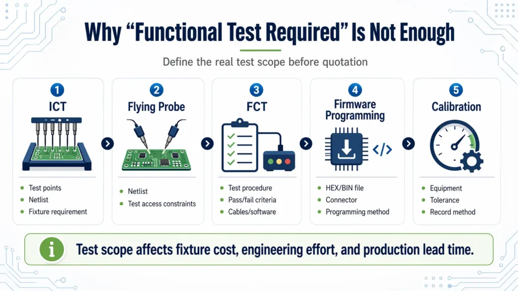
Many buyers write “functional test required” and assume the supplier knows what that means. In practice, functional testing can range from a simple power-on check to a fully automated test system with fixtures, cables, software, data logging, and calibration.
Why “functional test required” is not enough
“Functional test required” does not define:
- What needs to be tested
- How the board should be powered
- Which signals should be measured
- What pass/fail limits apply
- Whether a fixture is required
- Whether test software is supplied by the customer
- Whether the supplier must develop the test setup
- Whether data should be recorded
- Whether firmware programming is included
A simple power-on test may take little time. A full FCT setup may require fixture design, cable preparation, test program development, operator instructions, and engineering validation.
The quote should reflect the actual test scope, not a vague phrase.
Files needed for ICT, FCT, and programming
| Test or Programming Type | Useful RFQ Information |
|---|---|
| ICT | Test points, netlist, fixture requirement, coverage target |
| Flying Probe | Netlist, access limitations, prototype quantity |
| FCT | Test procedure, test sequence, input/output conditions, pass/fail limits |
| Firmware Programming | HEX/BIN file, programming tool, connector, programming method, verification method |
| Calibration | Required equipment, tolerance range, calibration steps, data recording method |
| Data Logging | Serial number rule, report format, traceability requirement |
| Visual Inspection | Cosmetic limits, polarity checks, labeling checks, acceptance criteria |
If the customer provides the fixture or test software, state that clearly. If the supplier is expected to develop them, that should also be included in the RFQ.
How test scope affects cost and lead time
Testing affects both one-time engineering cost and recurring production cost.
| Cost or Schedule Factor | Impact |
|---|---|
| Fixture design | Adds NRE and preparation time |
| Test software development | Requires engineering effort before production |
| Custom cables or interface boards | Adds material and preparation work |
| Manual test steps | Increase operator time per board |
| Automated test station | Higher setup cost, but may reduce cycle time in volume production |
| Calibration | Adds equipment, procedure, and data control requirements |
| Data logging | Adds traceability and reporting work |
| Aging or burn-in | Extends total production cycle time |
Testing should be discussed before the quote is finalized, not after the purchase order is placed.
Revision Control: The Most Overlooked Part of a PCBA RFQ Package
Revision control is often more important than the number of files in the package.
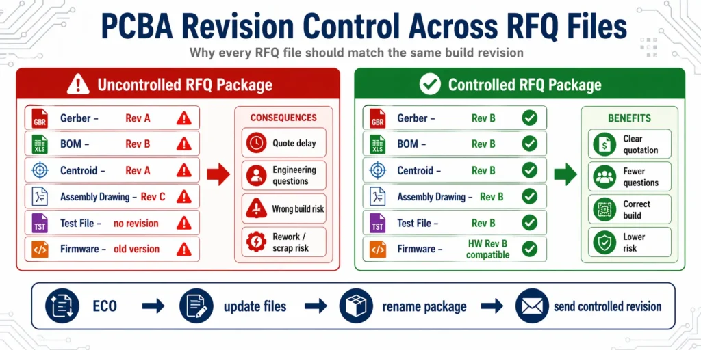
A supplier may receive a complete Gerber, a complete BOM, a complete centroid file, and a complete test procedure. But if they belong to different design revisions, the RFQ package is not controlled.
Why all files must belong to the same build revision
A PCBA build is driven by a connected set of files. Gerber defines the board. BOM defines the parts. Centroid defines placement. Assembly drawing clarifies orientation and special instructions. Test procedure defines acceptance. Firmware may define the final operating behavior.
If those files are not aligned, several problems can appear:
| Revision Problem | Possible Risk |
|---|---|
| Gerber is Rev A, BOM is Rev B | Footprints and part packages may not match |
| Centroid is exported from an old design | SMT placement may be wrong |
| Assembly drawing is newer than the BOM | DNP or orientation notes may conflict |
| Test procedure is based on old hardware | Good boards may fail or faults may be missed |
| Firmware does not match hardware revision | Programming or functional validation may fail |
| Change log is missing | Supplier cannot see what changed after ECO |
Before sending the RFQ, check that every file belongs to the same build revision.
Recommended RFQ file naming structure
A clear naming structure reduces confusion for both engineering and purchasing teams.
A good RFQ ZIP file name could be:
ProjectName_BoardName_RevB_RFQ_2026-04-20.zip
Inside the package:
| File Type | Example File Name |
|---|---|
| Gerber | Gerber_ProjectName_BoardName_RevB.zip |
| BOM | BOM_ProjectName_BoardName_RevB.xlsx |
| Centroid | Centroid_ProjectName_BoardName_RevB.csv |
| Assembly Drawing | AssemblyDrawing_ProjectName_BoardName_RevB.pdf |
| Fabrication Drawing | FabDrawing_ProjectName_BoardName_RevB.pdf |
| Test Procedure | FCT_Procedure_ProjectName_BoardName_RevB.pdf |
| Firmware | Firmware_ProjectName_BoardName_HWRevB_v1.2.hex |
| Change Log | ChangeLog_ProjectName_BoardName_RevB.pdf |
The exact naming rule can vary. The important point is that every file clearly shows the project, board name, revision, and purpose.
What to do after an ECO or design change
After an ECO or design update, do not send only the changed file. A controlled revision update should check every affected document.
| File | What to Check After ECO |
|---|---|
| Gerber / ODB++ | Updated traces, pads, drill data, board outline, or layer changes |
| BOM | Added, removed, or changed components |
| Centroid | Updated coordinates, rotation, side, and reference designators |
| Assembly Drawing | Updated layout, polarity, DNP notes, or special instructions |
| Test Files | Updated ICT netlist, FCT procedure, test limits, or access points |
| Firmware | Hardware-related software or configuration changes |
| Change Log | Clear record of what changed and why |
A revision note or change log helps the supplier understand the design change quickly and adjust quotation, tooling, sourcing, or testing assumptions.
Define the controlling document before quoting
Sometimes files conflict. A BOM may show one package, while the PCB footprint suggests another. A drawing may show a note that does not match the BOM. A firmware file may reference a different hardware revision.
To reduce confusion, define which document controls which part of the build:
| Build Area | Typical Controlling Document |
|---|---|
| PCB fabrication | Gerber / ODB++ and fabrication drawing |
| Component identity | BOM and approved manufacturer part number |
| SMT placement | Centroid file, checked against assembly drawing |
| Orientation and polarity | Assembly drawing and silkscreen reference |
| Testing | Test procedure and pass/fail criteria |
| Firmware | Programming file and programming instruction |
This does not replace engineering review, but it gives both sides a clearer path when conflicts appear.
Commercial and Supply Chain Information to Include in the RFQ
A PCBA RFQ package should include technical files and commercial information. Without commercial context, the supplier cannot quote the project under realistic production conditions.
Quantity, annual demand, and quote breaks
| Project Stage | Example Information to Provide |
|---|---|
| Prototype | Initial engineering quantity |
| Validation build | EVT/DVT/PVT quantity if applicable |
| Pilot run | Small production quantity for process verification |
| Mass production | Expected order quantity |
| Annual demand | Forecast for long-term sourcing and capacity planning |
| Quote breaks | Quantities such as 100, 500, 1,000, or 5,000 pcs if relevant |
Quantity affects setup cost allocation, material pricing, production planning, and purchasing strategy.
Lead time target and flexibility
Lead time should be stated clearly. It should also be clear whether the deadline is fixed or flexible.
A PCBA lead time can be affected by:
- PCB fabrication
- Component availability
- Stencil and fixture preparation
- SMT scheduling
- Through-hole or manual assembly
- ICT/FCT setup
- Firmware programming
- Packaging and shipment
If the project is urgent, state the required date. If there is schedule flexibility, mention it. This helps the supplier avoid unnecessary expedite assumptions.
Turnkey, consigned, or partial-turnkey responsibility
The RFQ should clearly define the sourcing model.
| Model | Responsibility |
|---|---|
| Turnkey | Supplier sources PCB, components, assembly, and related production services |
| Consigned | Customer supplies components; supplier provides assembly and related services |
| Partial Turnkey | Some parts are customer-supplied; others are sourced by the supplier |
For consigned or partial-turnkey projects, include:
- Customer-supplied part list
- Quantity provided
- Attrition allowance
- Packaging format
- Moisture-sensitive handling requirement
- Labeling method
- Shortage policy
- Whether parts are already programmed
This avoids production delays caused by unclear material responsibility.
Approved suppliers, alternates, and sourcing restrictions
If your project has strict sourcing rules, include them during RFQ.
Examples include:
- Approved vendor list
- Required component brands
- Authorized distributor requirement
- No substitution without approval
- Approved alternate parts
- Critical parts that cannot be changed
- RoHS or lead-free requirement
- Traceability requirement
Clear sourcing rules help the supplier quote against the correct material strategy.
Common RFQ Package Problems and How to Avoid Them
Many RFQ delays come from a small number of recurring issues.
| Problem | Why It Matters | How to Avoid It |
|---|---|---|
| BOM, Gerber, and centroid are from different revisions | Supplier may quote or build a file set that does not match | Send one controlled package with the same revision across all files |
| MPN is missing or ambiguous | Supplier cannot source the exact part reliably | Include complete manufacturer part numbers and manufacturer names |
| Test requirements are not defined | Test cost, fixture work, and cycle time cannot be quoted accurately | Provide test procedure, pass/fail limits, fixture needs, and software notes |
| DNP/DNI parts are not clearly marked | Parts may be quoted, purchased, or installed by mistake | Add a clear DNP/DNI column in the BOM and mark it in the drawing |
| Customer-supplied parts are mixed with turnkey parts | Responsibility and cost structure become unclear | Separate consigned and supplier-sourced parts in the BOM |
| Quantity, lead time, or packaging is missing | Quote assumptions may not match project needs | Provide quote breaks, target lead time, shipping destination, and packaging preference |
| Firmware or programming method is missing | Programming may become a late-stage bottleneck | Include firmware file, connector, tool, method, and verification requirement |
| Special processes are not mentioned | Coating, potting, cleaning, or labeling cost may be excluded | Add special process drawings or notes before quotation |
A good RFQ package is not simply more documents. It is a clearer manufacturing instruction set.
PCBA RFQ Package Checklist Before You Send Files
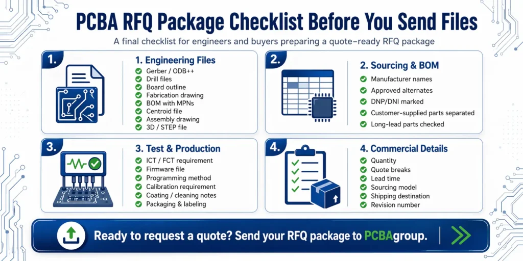
Engineering file checklist
- Gerber or ODB++ files
- NC drill files
- Board outline
- Fabrication drawing
- BOM with MPNs
- Centroid / pick-and-place file
- Assembly drawing
- Schematic, if available
- Panelization drawing, if available
- 3D / STEP file, if mechanical fit matters
- Current revision number for every file
Component and sourcing checklist
- Are all manufacturer part numbers included?
- Are manufacturer names included?
- Are packages and footprints clear?
- Are approved alternates listed?
- Are critical parts marked?
- Are DNP/DNI parts clearly identified?
- Are customer-supplied parts separated?
- Are sourcing restrictions stated?
- Are long-lead or obsolete parts flagged?
Test and production checklist
- ICT requirement
- Flying probe requirement
- FCT procedure
- Pass/fail criteria
- Firmware file
- Programming method
- Calibration requirement
- Conformal coating or potting requirement
- Cleaning requirement
- Labeling requirement
- Traceability requirement
- Packaging requirement
Commercial checklist
- Prototype quantity
- Pilot run quantity
- Mass production quantity
- Annual forecast
- Quote breaks
- Target lead time
- Turnkey, consigned, or partial-turnkey preference
- Shipping destination
- Packaging preference
- Quality or compliance requirement
How PCBAgroup Reviews an RFQ Package
PCBAgroup reviews RFQ packages from both engineering and production perspectives. The purpose is not only to calculate a price, but also to identify risks before they affect sourcing, assembly, testing, or delivery.
File completeness review
The first step is to check whether the core manufacturing files are available:
- PCB fabrication data
- BOM
- Centroid file
- Assembly drawing
- Quantity
- Lead time target
- Sourcing model
- Testing requirement
- Special process notes
If important files are missing, our team can help clarify what is needed before the quote is finalized.
BOM and sourcing risk check
The BOM is reviewed for sourcing clarity and risk.
Typical checks include:
- Missing MPNs
- Ambiguous descriptions
- Package mismatches
- Long-lead components
- Obsolete or hard-to-source parts
- Approved alternate availability
- Customer-supplied material responsibility
- Critical component restrictions
This helps buyers avoid late sourcing surprises after the order is placed.
DFM, DFA, and DFT review
Depending on the project, our engineering team may review:
- Pad and footprint suitability
- Component spacing
- Polarity and orientation clarity
- SMT and through-hole process requirements
- Panelization method
- Test point access
- Fixture feasibility
- Manual assembly risk
- Special process requirements
These checks help improve manufacturability before production starts.
Quote clarification and engineering questions
If the RFQ package contains missing or conflicting information, we organize the open questions before final quotation.
Common clarification topics include:
- Which revision should be quoted?
- Are alternates allowed?
- Which parts are customer-supplied?
- Is functional testing required?
- Who provides the test fixture?
- Is firmware programming included?
- What acceptance standard applies?
- Are there special packaging or traceability requirements?
Clear answers at this stage reduce later price changes and production delays.
Final Recommendation: Send a Controlled RFQ Package, Not Just Random Files
A professional PCBA RFQ package is a controlled manufacturing information set. It should tell the supplier what to build, what to buy, how to assemble it, how to test it, and which revision to follow.
The goal is not to send every file available. The goal is to send the right files, clearly named, internally consistent, and tied to the same build revision.
The goal is clearer manufacturing instructions
A strong RFQ package answers four questions:
- What board should be fabricated?
- What components should be sourced and assembled?
- How should the PCBA be inspected, tested, programmed, and accepted?
- Which revision controls the build?
When these questions are answered clearly, the supplier can quote faster and with fewer assumptions.
What to send PCBAgroup for a faster quote
For a faster and more accurate PCBA quote, send PCBAgroup:
- Complete Gerber or ODB++ files
- BOM with manufacturer part numbers
- Centroid / pick-and-place file
- Assembly drawing
- Target quantity and quote breaks
- Target lead time
- Turnkey, consigned, or partial-turnkey preference
- Testing requirements
- Firmware or programming notes, if applicable
- Current revision number
- Special process, packaging, or traceability requirements
Our engineering team will review your RFQ package, check file completeness, identify BOM and sourcing risks, clarify DFM/DFA/DFT questions, and support your project from prototype to production.
Need a quote-ready PCBA review before production?
Send PCBAgroup your Gerber or ODB++ files, BOM, centroid file, assembly drawing, quantity, and test requirements. Our engineering team will review your RFQ package, check DFM/DFA/DFT risks, and help clarify sourcing, testing, and revision-control questions before quotation.
FAQ
What files are required for a PCBA quote?
For most PCBA quotes, you should provide Gerber or ODB++ files, BOM with manufacturer part numbers, centroid or pick-and-place file, assembly drawing, quantity, target lead time, sourcing model, and any testing or programming requirements.
Can I get a PCBA quote without a centroid file?
A preliminary quote may be possible without a centroid file, especially at an early design stage. However, the centroid file is important for SMT placement review, machine programming, and assembly cost accuracy. Providing it early reduces assumptions.
What BOM columns should I include for PCB assembly?
A quote-ready BOM should include reference designator, quantity per board, manufacturer part number, manufacturer name, description, package, approved alternates, DNP/DNI status, and customer-supplied part notes if applicable.
Why is the manufacturer part number important in a BOM?
The MPN identifies the exact component to be sourced. Generic descriptions such as “10k resistor” or “10µF capacitor” are not specific enough because parts with the same value can differ in package, tolerance, voltage rating, material, and reliability.
Do I need to provide test files for prototype assembly?
It depends on the board and the purpose of the prototype. For simple builds, basic inspection or power-on testing may be enough. For functional products, provide test steps, pass/fail limits, firmware, cables, software, and fixture requirements if they are needed.

2 回复