Table of Contents
Common BOM Mistakes That Delay PCB Assembly
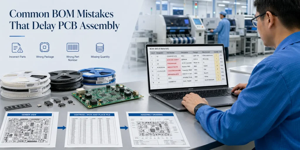
A PCB assembly delay often begins before the SMT line is even scheduled.
In many projects, the bottleneck is not solder paste printing, pick-and-place, reflow soldering, AOI inspection, X-ray inspection, or functional testing. The real issue starts earlier, with a Bill of Materials that is incomplete, unclear, or no longer aligned with the latest design files.
For engineers and purchasing teams, the BOM may look like a simple spreadsheet. For a PCB assembly manufacturer, it is one of the most important documents in the entire PCBA workflow.
The BOM tells the engineering team what to verify, the sourcing team what to purchase, the warehouse what to prepare, the SMT team what to mount, and the quality team what to inspect.
When the BOM is clear, the project can move faster from quotation to sourcing, kitting, production, and delivery. When the BOM is weak, every stage becomes slower. The supplier may need repeated clarification, purchasing may be paused, components may be ordered incorrectly, the kit may remain incomplete, or the SMT team may be unable to release the job to production.
This article explains the common BOM mistakes that delay PCB assembly and how to prepare a more production-ready BOM before sending your PCBA RFQ package.
Why BOM Accuracy Matters Before PCB Assembly Starts
A BOM is more than a component list. It connects design intent with sourcing, production planning, assembly execution, and quality control.
A well-prepared BOM helps the PCBA supplier review the project quickly, quote more accurately, source the right components, prepare the kit, program the SMT line, and control quality. A poor BOM creates uncertainty at each step.
The BOM Connects Engineering, Sourcing, Kitting, Assembly, and Quality Control
In a PCB assembly project, the BOM must align with other production files, including:
- Gerber or ODB++ files
- Pick-and-place / centroid file
- Assembly drawing
- Schematic
- PCB layout
- Test requirements
- Firmware or programming notes
- Revision history
Each document has a specific role.
Gerber or ODB++ files define the bare PCB. The centroid file tells the SMT machine where each component should be placed. The assembly drawing shows orientation, polarity, and special instructions. The BOM identifies the actual components that need to be purchased, prepared, mounted, and inspected.
If these files do not match, the assembler cannot safely decide which file should be followed.
For example:
- The BOM lists R10 as a 0603 resistor, but the PCB footprint is 0402.
- The centroid file includes U3, but U3 is missing from the BOM.
- The BOM is Rev B, while the Gerber file is Rev A.
- The assembly drawing marks one component as DNP, but the BOM does not.
Any of these issues can slow down quotation, sourcing, SMT programming, first article inspection, or production release.
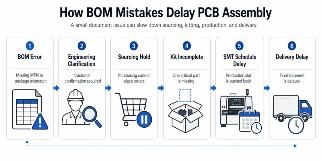
How a Small BOM Error Becomes a Production Delay
A small BOM error can move through the entire manufacturing chain and turn into a much larger delay.
A typical delay path looks like this:
BOM error → engineering clarification → sourcing hold → kit incomplete → SMT schedule delay → delivery delay
Here is how it usually happens:
- The BOM error is found
The supplier may notice that a package does not match the PCB footprint, a part number is incomplete, or a component listed in the centroid file is missing from the BOM. - Engineering clarification is required
The PCBA supplier cannot proceed based on assumptions. The engineering or sourcing team must ask the customer to confirm the correct part, footprint, or revision. - Purchasing is paused
Until the correct information is confirmed, the sourcing team cannot safely order the material. If the original part is wrong, price, stock, lead time, and approved alternates may need to be checked again. - The kit cannot be completed
Even if most parts are ready, one missing critical IC, connector, crystal, programmed part, or power component can prevent the build from reaching kit complete. - The SMT schedule is pushed back
Without a complete and verified kit, the production job cannot be released. The original SMT time slot may be reassigned to another project. - Final delivery is delayed
A mistake that could have been corrected quickly during file preparation may create days of delay once the project has entered sourcing and production planning.
This is why BOM accuracy should be treated as part of production readiness, not just document formatting.
What a Production-Ready PCB Assembly BOM Should Include
A production-ready BOM gives your PCBA supplier enough information to quote, source, verify, kit, assemble, inspect, and trace the build without unnecessary back-and-forth communication.
At minimum, a PCB assembly BOM should include the following fields.
| BOM Field | Why It Matters |
|---|---|
| Item number | Keeps each BOM line easy to identify and discuss |
| Reference designator | Connects each component to its physical PCB location |
| Quantity per board | Allows accurate material demand calculation |
| Manufacturer | Reduces brand ambiguity |
| Manufacturer Part Number | Identifies the exact component |
| Value / specification | Helps verify electrical requirements |
| Package / footprint | Confirms physical compatibility with PCB pads |
| Description | Supports engineering and purchasing review |
| DNP / DNI status | Shows which positions should not be populated |
| Approved alternates | Reduces delay when the primary part is unavailable |
| Source type | Clarifies supplier-sourced and customer-supplied parts |
| Notes | Records special handling, programming, compliance, or revision instructions |
A BOM does not need to be overly complex. It does, however, need to be unambiguous.
For prototypes, the main goal is fast engineering review and quick sourcing. For pilot runs, the BOM must support process validation and repeatable assembly. For mass production, it also needs to support supply stability, traceability, compliance, cost control, and revision control.
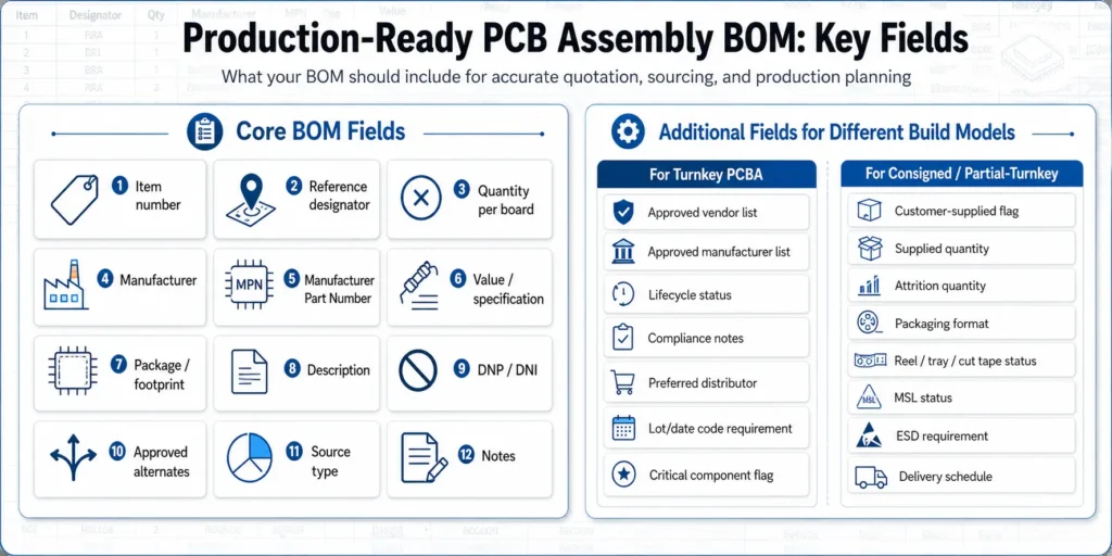
Extra BOM Fields for Turnkey PCB Assembly
In turnkey PCB assembly, the manufacturer handles component sourcing, PCB fabrication or coordination, assembly, inspection, and often testing.
Because the supplier is responsible for sourcing, the BOM must provide enough detail for accurate purchasing decisions.
For turnkey PCBA projects, consider adding the following fields:
| Extra Field | Why It Helps |
|---|---|
| Approved vendor list | Defines acceptable sourcing channels |
| Approved manufacturer list | Prevents unwanted brand substitutions |
| Alternate approval rule | Clarifies when substitutes are allowed |
| Lifecycle status | Helps identify EOL, NRND, or obsolete parts |
| RoHS / REACH / compliance notes | Supports regulated markets |
| Target cost or cost limit | Helps control cost-sensitive components |
| Preferred distributor | Supports traceable procurement |
| Lot code / date code requirement | Helps meet traceability requirements |
| Critical component flag | Highlights parts that need stricter control |
For turnkey assembly, a vague BOM slows down the entire process. The supplier must ask more questions before quoting, sourcing, and committing to lead time.
Extra BOM Fields for Consigned or Partial-Turnkey Builds
In consigned PCB assembly, the customer supplies all components. In partial-turnkey assembly, the customer supplies some parts while the PCBA supplier sources the rest.
These models can work well, but only when the BOM clearly defines who is responsible for each material and what condition the supplied parts must meet.
For consigned or partial-turnkey builds, add these fields where relevant:
| Extra Field | Why It Helps |
|---|---|
| Customer-supplied flag | Shows which parts the customer will provide |
| Supplier-sourced flag | Shows which parts the assembler should purchase |
| Supplied quantity | Confirms how many parts will arrive at the factory |
| Attrition / spare quantity | Prevents shortages caused by normal SMT loss |
| Packaging format | Helps plan feeder setup and material handling |
| Reel / cut tape / tray / tube status | Confirms SMT readiness |
| MSL status | Identifies moisture-sensitive parts |
| ESD handling requirement | Reduces electrostatic damage risk |
| Labeling requirement | Helps warehouse and IQC match parts to the BOM |
| Delivery schedule | Helps the supplier plan receiving, storage, and production |
For consigned material, the correct part number is not enough. The material must also arrive in the right quantity, packaging, condition, label format, and timing.
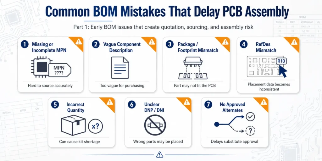
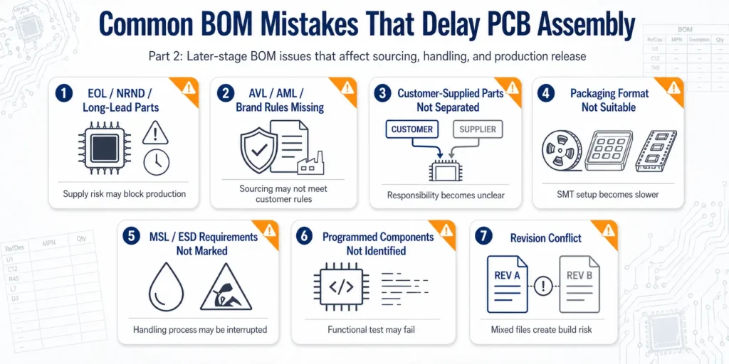
Common BOM Mistakes That Delay PCB Assembly
1. Missing or Incomplete Manufacturer Part Numbers
The Manufacturer Part Number, or MPN, is one of the most important fields in a PCB assembly BOM.
An MPN identifies the exact component required by the design. It can define the package, tolerance, voltage rating, temperature coefficient, power rating, material grade, manufacturer series, and lifecycle status.
A vague BOM entry like this is not enough for accurate turnkey PCB assembly:
| RefDes | Description | Package |
|---|---|---|
| R1, R2 | 10k resistor | 0603 |
This entry gives the supplier a value and a package, but it does not define:
- Manufacturer
- Exact MPN
- Tolerance
- Power rating
- Temperature coefficient
- Voltage rating
- Quality grade
- Substitute rule
A stronger BOM entry would look like this:
| RefDes | Qty | Manufacturer | MPN | Value / Specification | Package | Notes |
|---|---|---|---|---|---|---|
| R1, R2 | 2 | Yageo | RC0603FR-0710KL | 10kΩ, 1%, 1/10W | 0603 | Alternate acceptable |
For simple passive components, some customers allow the PCBA supplier to select equivalent parts. That can work if the rule is clearly stated. For ICs, connectors, sensors, crystals, RF components, power devices, safety-related parts, and customer-approved parts, the exact MPN should be provided.
Without a complete MPN, the supplier may quote based on assumptions. Later, when the exact component is confirmed, the real cost, availability, or lead time may be different. This leads to quotation changes, sourcing delays, and unnecessary communication loops.
2. Using Vague Component Descriptions Instead of Controlled Part Data
Generic component descriptions may be clear to the design team, but they are risky in manufacturing.
Examples include:
- “Capacitor 104”
- “10k resistor”
- “USB connector”
- “MCU”
- “LED red”
- “Diode”
- “Crystal”
- “Power IC”
These descriptions do not give the sourcing team enough controlled data.
For example, “100nF capacitor” does not define:
- Package size
- Rated voltage
- Tolerance
- Dielectric material
- Temperature behavior
- Manufacturer
- MPN
- Approved alternates
A purchasing team may choose a low-cost part that appears similar but does not meet the design requirement. In repeat production, another purchasing cycle may choose a different “equivalent” component, creating batch-to-batch variation.
A production-ready BOM should use controlled component data, not informal descriptions.
A good entry should include:
- Complete MPN
- Manufacturer
- Electrical value
- Package
- Key specification
- Approved alternate rule
- Source responsibility
Descriptions should support the MPN. They should not replace it.
3. Package or Footprint Mismatch Between BOM and PCB Layout
Package mismatch is one of the most disruptive BOM mistakes.
It happens when the package listed in the BOM does not match the footprint in the PCB layout.
Common examples include:
- BOM says 0603, but the PCB footprint is 0402.
- BOM says SOT-23, but the layout uses SOT-223.
- An IC part number is electrically correct but uses the wrong package suffix.
- A connector series has multiple heights, orientations, or pin configurations.
- The BOM package name does not match the CAD footprint.
- A schematic symbol was updated, but the PCB footprint was not.
This mistake can be hard to catch during purchasing because the part may appear electrically correct. The problem often becomes visible when the material arrives and the SMT team prepares feeder setup, stencil alignment, or first article inspection.
The result may be:
- The part cannot be mounted.
- The solder pads do not match the lead structure.
- Reflow soldering creates poor joints or tombstoning.
- An alternative part must be sourced urgently.
- The PCB layout must be revised.
- Existing bare PCBs may need to be scrapped.
Before sending the BOM to a PCBA supplier, verify that each package in the BOM matches the PCB footprint, especially for connectors, ICs, crystals, relays, transformers, power components, and custom mechanical parts.
4. Reference Designators Do Not Match BOM, Schematic, and Centroid Files
Reference designators connect the BOM to the physical board.
If the BOM says a component is placed at R1, R2, and R3, the centroid file and assembly drawing should show the same positions.
Reference designator mismatches create problems for:
- SMT programming
- Feeder assignment
- AOI programming
- First article inspection
- Manual inspection
- Rework and troubleshooting
- Functional failure analysis
Common problems include:
- The BOM lists parts not found in the centroid file.
- The centroid file includes placements missing from the BOM.
- The same reference designator is used twice.
- Reference designators are removed during revision updates.
- Ranges are unclear, such as “R1-R10” when R4 and R7 are DNP.
- Variant BOMs are mixed together.
- The schematic, BOM, and assembly drawing use different designator names.
A clear BOM should list reference designators consistently.
Good example:
R1, R2, R3, R5, R8
Risky example:
R1-R8 except some
If some positions are not populated, mark them clearly as DNP or DNI. Do not rely on hidden rows, cell colors, or informal comments.
5. Incorrect Quantities or Unclear Quantity per Board
Quantity errors affect cost, sourcing, and kitting immediately.
A BOM should clearly show the quantity required per finished board. It should not confuse:
- Quantity per board
- Total order quantity
- Panel quantity
- Spare quantity
- Attrition quantity
- Customer-supplied quantity
- Production build quantity
For example, if one PCBA uses four capacitors and the order quantity is 500 boards, the theoretical requirement is 2,000 capacitors before attrition.
If the BOM only shows “2,000” without explaining whether it means total quantity or quantity per build, the supplier must stop and clarify.
This becomes more important in consigned or partial-turnkey projects. If the customer supplies only the exact theoretical quantity, normal SMT attrition may leave the production team short of usable parts.
For customer-supplied materials, confirm:
- Required quantity per board
- Total build quantity
- Extra parts for attrition
- Spare parts for setup and inspection
- Higher reserve quantity for critical components, if needed
- Whether the supplied quantity matches the BOM
A small quantity error can prevent the build from reaching kit complete.
6. DNP / DNI Parts Are Missing or Unclear
DNP means Do Not Populate. DNI means Do Not Install.
In most PCB assembly projects, both terms mean that a component position should not be mounted during this build. The exact term matters less than consistency.
Unclear DNP/DNI markings can cause several problems:
- The supplier quotes unnecessary components.
- Purchasing buys parts that are not needed.
- The SMT team mounts parts that should be left empty.
- A required part is skipped by mistake.
- Variant builds are mixed.
- Engineering clarification is required before production.
Do not simply delete DNP parts from the BOM if the pads still exist on the PCB. The assembler needs to know that those positions are intentionally empty.
A better approach is to add a dedicated DNP/DNI column.
| RefDes | MPN | Qty | DNP/DNI |
|---|---|---|---|
| R10 | RC0603FR-0710KL | 1 | No |
| R11 | RC0603FR-0710KL | 1 | Yes |
For product variants, such as standard version, RF version, EU version, or battery-powered version, create separate variant BOMs or add clear variant columns.
DNP/DNI information should also be consistent across the BOM, assembly drawing, and schematic notes.
7. No Approved Alternates When the Primary Part Is Unavailable
Component availability can change quickly. A part that is available during design may become expensive, allocated, long-lead, NRND, or unavailable during sourcing.
If the BOM lists only one primary part and no approved alternates, the project may stop when that part becomes unavailable.
This is especially important for:
- Passives
- MOSFETs
- Regulators
- Connectors
- LEDs
- Crystals
- Sensors
- Power ICs
- Long-lead components
- Parts with known allocation risk
A strong BOM may include:
- Primary MPN
- Alternate manufacturer
- Alternate MPN
- Whether substitution is allowed
- Whether customer approval is required
- Whether the alternate has been electrically verified
- Whether the alternate is pin-to-pin and footprint-compatible
Not all alternates are equal. Some may match the electrical value but differ in tolerance, thermal behavior, package, pinout, firmware compatibility, or reliability.
For non-critical passives, approved equivalents can reduce sourcing delays. For critical ICs, sensors, RF parts, safety-related parts, and power components, alternates should be reviewed carefully before production.
8. Obsolete, EOL, NRND, or Long-Lead Components Are Not Flagged Early
A BOM can look complete and still contain serious sourcing risk.
Some components may be:
- EOL: End of Life
- NRND: Not Recommended for New Designs
- Obsolete
- Out of stock
- Available only through brokers
- Subject to long lead times
- Available only with high MOQ
- Risky for repeat production
- Unsuitable for future mass production
These risks may not matter during a one-time prototype if small quantities are available. They become much more serious when the project moves to pilot run or mass production.
For example:
- A prototype may use a component found in small stock.
- A pilot run may need stable short-term supply.
- Mass production needs long-term availability, traceability, and repeatable quality.
If lifecycle risks are found late, the project may require redesign, requalification, customer approval, or new functional testing.
A better approach is to review BOM health early. Identify long-lead, EOL, NRND, or high-risk components before the production schedule depends on them.
9. AVL, AML, or Brand Restrictions Are Not Clearly Defined
For many industrial, medical, automotive, aerospace, telecom, and high-reliability electronics projects, sourcing is not simply a matter of buying the same part number.
The customer may have rules such as:
- Use only approved manufacturers.
- Use only authorized distributors.
- Do not purchase from brokers.
- Do not substitute without written approval.
- Use specific brands for critical components.
- Provide traceability records.
- Meet RoHS, REACH, or other compliance requirements.
- Follow customer-approved AVL or AML lists.
If these rules are not shared during RFQ, the supplier may quote based on a technically equivalent but commercially unacceptable source.
This can lead to:
- Re-quotation
- Re-sourcing
- Customer rejection
- Compliance concerns
- Traceability gaps
- Delayed production release
If your project has approved vendor or manufacturer requirements, include them in the BOM, RFQ notes, or a separate AVL/AML file.
Example:
| RefDes | MPN | Manufacturer Rule | Distributor Rule |
|---|---|---|---|
| U1 | TPSxxxx | TI only | Authorized distributor only |
| C1-C20 | 100nF 0603 | Murata / TDK / Samsung OK | Flexible |
| J1 | USB-C connector | Customer-approved part only | Approval required |
This helps the supplier quote and source according to your real requirements from the beginning.
10. Customer-Supplied Parts Are Not Separated from Supplier-Sourced Parts
Partial-turnkey assembly is flexible, but it creates risk when sourcing responsibility is unclear.
The customer may assume the factory will buy a part. The factory may assume the customer will supply it. Both sides may wait, and the part may not be ordered at all.
This issue often appears only when the project is close to production and the kit is incomplete.
To prevent this, add a source type column.
| RefDes | MPN | Source Type | Notes |
|---|---|---|---|
| U1 | STM32xxxx | Customer-supplied | Programmed IC |
| R1-R20 | RC0603FR series | Supplier-sourced | Alternate OK |
| J1 | USB-C connector | Customer-supplied | Customer-approved part |
| C1-C10 | GRM series | Supplier-sourced | Equivalent OK |
For customer-supplied parts, also confirm:
- Supplied quantity
- Spare quantity
- Delivery schedule
- Packaging format
- Labeling
- MSL status
- ESD protection
- Whether parts are programmed or blank
- Whether the material is suitable for automated SMT placement
Partial-turnkey projects should treat the BOM as a responsibility matrix, not only a component list.
11. Packaging Format Is Missing or Unsuitable for SMT Production
A component can have the correct MPN and still delay production if its packaging is not suitable for assembly.
Common packaging formats include:
- Reel
- Cut tape
- Tray
- Tube
- Loose parts
- Bulk parts
For automated SMT assembly, reels and trays are usually easier to handle. Short cut tape, loose parts, mixed bags, or poorly labeled materials require extra manual work and may increase setup time, error risk, and attrition.
Packaging issues are especially common in consigned projects.
Examples include:
- Cut tape is too short for feeder setup.
- Components arrive loose in a bag.
- Multiple MPNs are mixed together.
- Labels are missing or inconsistent.
- Moisture-sensitive parts are not sealed correctly.
- ESD-sensitive parts are not packaged properly.
- Tray orientation is not documented.
- Customer-supplied material does not include spare quantity.
If you supply parts to your PCBA manufacturer, confirm packaging format before shipment. The lowest purchase price is not always the lowest production cost if the packaging slows down SMT setup.
12. Moisture-Sensitive or ESD-Sensitive Parts Are Not Marked
Some components require special handling before assembly.
Moisture-sensitive devices may need dry storage, vacuum sealing, humidity indicator cards, baking, or controlled exposure time before reflow. ESD-sensitive devices require anti-static packaging and handling.
If the BOM or consigned material list does not flag these requirements, the factory may need to stop during IQC or production preparation to verify the correct handling process.
This can delay:
- Incoming inspection
- Baking preparation
- SMT scheduling
- Reflow readiness
- Quality approval
For consigned materials, include handling notes for:
- MSL level
- Open bag exposure time
- Baking requirement
- Dry pack condition
- ESD requirement
- Special storage temperature
- Shelf-life limitation
These details help prevent soldering defects, hidden reliability issues, and production holds.
13. Programmed or Serialized Components Are Not Clearly Identified
Some components are not standard blank parts. They may require firmware programming, serialization, calibration, or customer-specific data.
Examples include:
- MCUs
- EEPROMs
- Flash memory
- Wireless modules
- Security ICs
- Pre-programmed controllers
- Calibrated sensors
- Modules with MAC addresses or serial numbers
If the BOM does not identify these parts clearly, assembly may be delayed during testing or functional validation.
For programmed parts, include:
- Whether the part is blank or pre-programmed
- Firmware version
- Programming file name
- Programming method
- Labeling or serialization rule
- Whether programming is done before or after assembly
- Whether customer approval is required before mass production
A PCB can be assembled correctly and still fail functional testing if programmed component information is missing.
14. BOM Revision Does Not Match Gerber, Centroid, or Assembly Drawing
Mixed revisions are one of the most dangerous causes of PCB assembly delay.
A project may include:
- BOM Rev B
- Gerber Rev A
- Centroid Rev C
- Assembly drawing Rev B
- Test instruction Rev A
When files come from different revisions, the manufacturer cannot safely decide which version to follow.
Revision mismatch can cause:
- Wrong components purchased
- Components placed on old footprints
- Missing placements
- Extra placements
- DNP positions misunderstood
- Polarity or orientation conflicts
- Assembly drawing conflicts
- Engineering hold
- Rework or scrap risk
Before sending production files, confirm that all files are exported from the same design revision.
Use clear file names such as:
ProjectName_BOM_RevB_2026-04-27.xlsxProjectName_Gerber_RevB_2026-04-27.zipProjectName_Centroid_RevB_2026-04-27.csvProjectName_AssemblyDrawing_RevB_2026-04-27.pdf
If a design change has been made, include a short revision note. Do not send updated files without explaining what changed.
How BOM Mistakes Delay the PCB Assembly Workflow
Quotation Delay: The Supplier Cannot Confirm Real Cost
If the BOM is missing MPNs, manufacturer names, package information, or quantity clarity, the supplier cannot calculate accurate material cost.
The quoting team may need to ask:
- Which exact part should be used?
- Is this part customer-approved?
- Are equivalents allowed?
- Is the listed package correct?
- Is this part DNP or populated?
- Who will supply this part?
- Are there compliance or traceability requirements?
Every unanswered question slows down quotation. In cross-border projects, even a simple clarification loop can take one or more business days.
Sourcing Delay: Purchasing Cannot Order the Right Parts
Purchasing teams rely on the BOM to source components.
If the BOM is vague, sourcing may be paused. If the BOM is wrong, the wrong parts may be purchased.
Sourcing delays often come from:
- Missing MPNs
- Wrong package suffixes
- Unclear approved alternates
- AVL restrictions shared too late
- EOL or NRND parts
- Long-lead components
- Customer approval required for substitutes
- Compliance rules not stated early
For turnkey assembly, sourcing speed depends heavily on BOM clarity.
Kitting Delay: The Build Cannot Reach Kit Complete
A PCB assembly job cannot move smoothly into production unless the required materials are ready.
Kit incomplete problems may come from:
- Incorrect component quantities
- Missing customer-supplied parts
- Insufficient attrition quantity
- DNP confusion
- Delayed long-lead parts
- Incorrect or rejected incoming material
- Unclear source responsibility
One missing critical part can delay the entire SMT schedule.
SMT Delay: Machine Programming Needs Consistent Data
SMT programming depends on alignment between the BOM, centroid file, assembly drawing, and PCB layout.
If these files are inconsistent, the SMT team may need to stop and clarify before setup.
Problems may include:
- RefDes mismatch
- Wrong footprint
- Polarity conflict
- Rotation angle conflict
- DNP not shown consistently
- Wrong package in BOM
- Mixed revision files
These issues can delay feeder setup, machine programming, first article inspection, AOI programming, and production release.
Quality Delay: Traceability and Compliance Need Clear Rules
For high-reliability products, quality control depends on clear BOM data.
The BOM may need to support:
- Incoming inspection
- Component authenticity review
- Lot code traceability
- Date code control
- RoHS / REACH compliance
- Customer AVL requirements
- Critical component tracking
- Functional test preparation
If these requirements are not stated before sourcing and production, they may cause delays during IQC, final inspection, customer audit, or shipment.
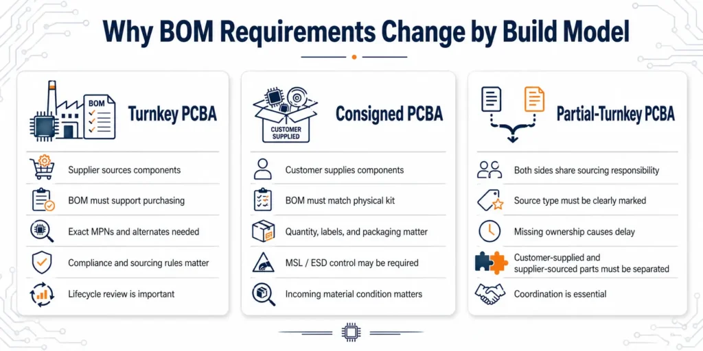
Turnkey vs Consigned PCBA: Why BOM Requirements Are Different
In Turnkey PCBA, the BOM Drives Sourcing Responsibility
In turnkey PCB assembly, the supplier sources the components and manages assembly. The BOM becomes the sourcing instruction.
The supplier needs to know:
- Exact MPNs
- Manufacturer names
- Approved alternates
- Substitute rules
- Compliance requirements
- AVL restrictions
- Lifecycle risks
- Critical components
- DNP/DNI positions
- Revision status
If the BOM is incomplete, the supplier cannot make reliable sourcing decisions. This delays quotation, purchasing, and kit completion.
In Consigned PCBA, the BOM Must Match the Physical Kit
In consigned PCB assembly, the customer supplies the components. The BOM becomes the receiving and kitting standard.
The supplier checks whether the physical material matches the BOM.
Important questions include:
- Did the customer send the correct MPN?
- Is the quantity enough?
- Are spare parts included?
- Is the packaging suitable for SMT?
- Are labels clear?
- Are MSL and ESD requirements controlled?
- Are programmed parts identified?
- Do physical parts match BOM descriptions?
If the material kit does not match the BOM, production cannot start smoothly.
In Partial-Turnkey PCBA, Unclear Ownership Creates the Most Delays
Partial-turnkey assembly combines both models. The customer supplies key parts, and the supplier sources the rest.
This model works well when responsibility is clear. It becomes risky when responsibility is vague.
Every BOM line should clearly show one of the following:
- Customer-supplied
- Supplier-sourced
- Not populated
- To be confirmed
Avoid vague notes such as:
- “Maybe customer provides”
- “Factory can check”
- “Depends on stock”
- “Will confirm later”
These notes create uncertainty. Uncertainty delays sourcing, kitting, and production release.
How to Review Your BOM Before Sending It to a PCBA Supplier
Step 1: Export the BOM from the Latest ECAD Project
Do not reuse an old spreadsheet that has been manually edited many times.
Export the BOM from the latest schematic or PCB design project whenever possible. This reduces the risk of old reference designators, outdated footprints, removed components, or incorrect quantities.
Step 2: Check Every MPN, Package, and Reference Designator
Review every production-critical part.
Pay extra attention to:
- ICs
- Connectors
- Crystals
- Sensors
- RF parts
- Power components
- Displays
- Transformers
- Relays
- Programmed components
Make sure the MPN is complete, the package is correct, and the reference designator exists in the design files.
Step 3: Mark DNP/DNI and Customer-Supplied Parts Clearly
Use dedicated columns for DNP/DNI status and source responsibility.
Do not rely on:
- Cell color
- Hidden rows
- Informal comments
- Separate email notes
- Unclear abbreviations
A PCBA supplier should be able to open the BOM and immediately understand which parts are populated, which are not, which are customer-supplied, and which are supplier-sourced.
Step 4: Add Approved Alternates and Approval Rules
For each substitute, clarify:
- Is it fully approved?
- Is it only approved for prototype?
- Does it require customer approval?
- Is it pin-to-pin compatible?
- Is the footprint identical?
- Does it affect firmware, calibration, or testing?
- Can the supplier use it automatically if the primary part is unavailable?
This avoids urgent approval loops during sourcing.
Step 5: Confirm Lifecycle, Stock, Lead Time, and Compliance
Before production, check whether key parts are:
- Active
- Available
- Reasonably priced
- Suitable for future production
- Compliant with project requirements
- Traceable through acceptable channels
For mass production, this step is especially important.
Step 6: Align BOM Revision with Gerber, Centroid, and Assembly Drawing
Before sending files, check that all files use the same revision.
The BOM, Gerber, centroid file, assembly drawing, test instructions, and firmware notes should describe the same build.
If you send a revised file later, include:
- New revision number
- Change summary
- Date
- Reason for update
- Whether old files should be discarded
Revision control protects both the customer and the manufacturer.
PCBA BOM Readiness Checklist Before RFQ
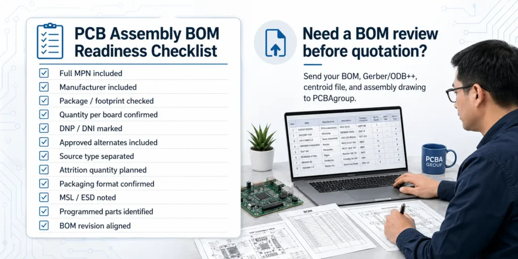
Use this checklist before requesting a PCB assembly quote.
| Check Item | Why It Matters | Ready? |
|---|---|---|
| Full MPN included | Prevents wrong sourcing and quote assumptions | □ |
| Manufacturer included | Avoids brand ambiguity | □ |
| Value and key specification included | Helps verify electrical requirements | □ |
| Package / footprint checked | Prevents assembly mismatch | □ |
| Quantity per board confirmed | Prevents material shortage or overbuying | □ |
| Reference designators match centroid file | Supports SMT programming | □ |
| DNP/DNI positions marked | Prevents wrong purchasing and placement | □ |
| Approved alternates included | Reduces shortage-related delay | □ |
| AVL / brand restrictions listed | Supports compliance and customer sourcing rules | □ |
| Customer-supplied parts separated | Prevents responsibility confusion | □ |
| Attrition quantity planned | Reduces consigned material shortage risk | □ |
| Packaging format confirmed | Supports SMT feeder setup and kitting | □ |
| MSL / ESD requirements noted | Prevents handling and reliability issues | □ |
| Programmed parts identified | Prevents functional test delays | □ |
| BOM revision matches Gerber and centroid | Prevents mixed-revision production risk | □ |
| Test and programming notes included | Supports production and validation planning | □ |
Poor BOM vs Production-Ready BOM Example
Poor BOM Example
| RefDes | Description | Qty | Package |
|---|---|---|---|
| R1-R5 | 10k resistor | 5 | 0603 |
| C1-C3 | capacitor | 3 | 0603 |
| U1 | MCU | 1 | QFP |
| J1 | connector | 1 | USB |
Problems:
- No manufacturer
- No complete MPN
- No tolerance or voltage rating
- No clear package variant
- No source responsibility
- No DNP/DNI field
- No approved alternates
- No revision information
Production-Ready BOM Example
| RefDes | Qty | Manufacturer | MPN | Value / Description | Package | DNP/DNI | Source | Notes |
|---|---|---|---|---|---|---|---|---|
| R1-R5 | 5 | Yageo | RC0603FR-0710KL | 10kΩ, 1%, 1/10W | 0603 | No | Supplier | Equivalent OK |
| C1-C3 | 3 | Murata | GRM188R71C104KA01D | 100nF, 16V, X7R | 0603 | No | Supplier | Equivalent OK |
| U1 | 1 | STMicroelectronics | STM32xxxx | MCU | LQFP-48 | No | Customer | Programmed part |
| J1 | 1 | Amphenol | xxxx | USB-C connector | SMT | No | Supplier | Customer approval required |
This version gives the PCBA supplier enough information to quote, source, verify, and prepare production with fewer clarification loops.
How PCBAgroup Helps Reduce BOM-Related PCB Assembly Delays
A reliable PCBA supplier does more than place components on a PCB. It helps identify production risks before they become schedule problems.
PCBAgroup supports PCB assembly projects from prototype to volume production, including SMT assembly, through-hole assembly, component sourcing, inspection, and testing. For BOM-related risks, our team can review the information needed for quotation, sourcing, kitting, and production preparation.
BOM Review Before Quotation
Before production begins, a BOM review can help identify:
- Missing or incomplete MPNs
- Vague component descriptions
- Package or footprint risks
- RefDes mismatch
- Quantity problems
- DNP/DNI confusion
- Missing alternates
- EOL or long-lead parts
- Customer-supplied material risks
- Revision mismatch
Clarifying these issues before quotation helps avoid later changes in cost, sourcing plan, and production schedule.
Sourcing Risk Review for Turnkey PCBA
For turnkey projects, BOM quality directly affects component sourcing.
PCBAgroup can help check:
- Whether key parts are available
- Whether alternates may be needed
- Whether brand or distributor restrictions are clear
- Whether high-risk parts should be reviewed before production
- Whether critical components require customer approval
This helps reduce sourcing delays after the project has already been quoted.
Consigned and Partial-Turnkey Material Coordination
For consigned and partial-turnkey builds, BOM review should also cover customer-supplied material conditions.
Important checks include:
- Which parts are customer-supplied
- Whether the supplied quantity includes attrition
- Whether packaging is suitable for SMT
- Whether labels match the BOM
- Whether MSL or ESD handling is required
- Whether programmed parts are clearly identified
- Whether all customer-supplied parts will arrive before production
This helps prevent kit incomplete problems and production waiting time.
File Consistency Review Before Production Release
BOM review should not be isolated from the rest of the RFQ package. The BOM should be checked together with Gerber or ODB++ files, centroid data, assembly drawing, test notes, and revision history.
The goal is to clarify BOM risks before production release, not after the SMT line is waiting.
FAQ: BOM Mistakes in PCB Assembly
What is the most common BOM mistake in PCB assembly?
The most common BOM mistakes include missing MPNs, vague descriptions, package mismatches, unclear DNP/DNI markings, incorrect quantities, missing alternates, customer-supplied material confusion, and revision mismatch.
Can I send a BOM without manufacturer part numbers?
You can send a BOM without MPNs for early technical discussion, but it is not suitable for accurate turnkey PCB assembly quotation or formal production. Without MPNs, the supplier must make assumptions, which increases sourcing risk and delay.
What is the difference between DNP and DNI in a BOM?
DNP means Do Not Populate. DNI means Do Not Install. In most PCB assembly projects, both terms mean that a component position should not be mounted. The key is to use one term consistently and mark it clearly in the BOM and assembly drawing.
Should I include approved alternates in my BOM?
Yes, especially for schedule-sensitive or production projects. Approved alternates can reduce sourcing delays if the primary part is unavailable. Critical components should still be reviewed and approved by engineering before substitution.
Why does package mismatch delay PCB assembly?
A package mismatch means the physical component may not fit the PCB footprint. Even if the electrical value is correct, the part may be impossible to mount or solder reliably. This can lead to sourcing changes, engineering review, rework, or PCB redesign.
Why do customer-supplied parts delay consigned PCB assembly?
Customer-supplied parts can delay assembly if they arrive late, in insufficient quantity, with unclear labels, unsuitable packaging, missing MSL or ESD control, or without enough attrition quantity for SMT setup and production loss.
What files should I send together with the BOM?
For an accurate PCBA quote, send the BOM together with Gerber or ODB++ files, centroid / pick-and-place file, assembly drawing, test requirements, firmware or programming notes, and revision notes.
How can I reduce BOM-related PCB assembly delays?
Use complete MPNs, verify packages against PCB footprints, confirm quantities, mark DNP/DNI positions, add approved alternates, separate customer-supplied parts, define sourcing rules, check lifecycle risk, and keep all production files under the same revision.
Conclusion
A clean BOM protects your PCB assembly schedule.
Many PCBA delays do not begin on the production line. They begin with missing MPNs, vague component descriptions, package mismatches, unclear DNP/DNI marks, wrong quantities, missing alternates, consigned material problems, or mixed file revisions.
Before sending your next RFQ, review your BOM carefully. Make sure every component is clearly identified, every source responsibility is defined, every non-populated position is marked, every customer-supplied part is controlled, and every production file belongs to the same revision.
Preparing a prototype, pilot run, or production PCBA project?
Send PCBAgroup your BOM, Gerber or ODB++ files, centroid file, and assembly drawing. Our engineering and sourcing team can help review your files, identify BOM-related risks, clarify component sourcing responsibilities, and support a smoother path from quotation to PCB assembly.
Need a faster and more accurate PCBA quote? Upload your BOM and production files to PCBAgroup for review.
