Table of Contents
PCBA Production Lead Time Breakdown
Quality, lead time, and price are the three factors PCBA customers care about most when selecting a manufacturer. PCBAgroup can efficiently balance all three based on your priorities and provide the best value-for-money solution.
When customers ask about lead time, what they actually want is an executable PCBA timeline: what determines the duration of each phase, what must be prepared and run in parallel, which items become the critical path once delayed, and how to make delivery predictable and compressible without sacrificing quality or compliance.
What “Lead Time” Really Means
Lead Time Breakdown Formula
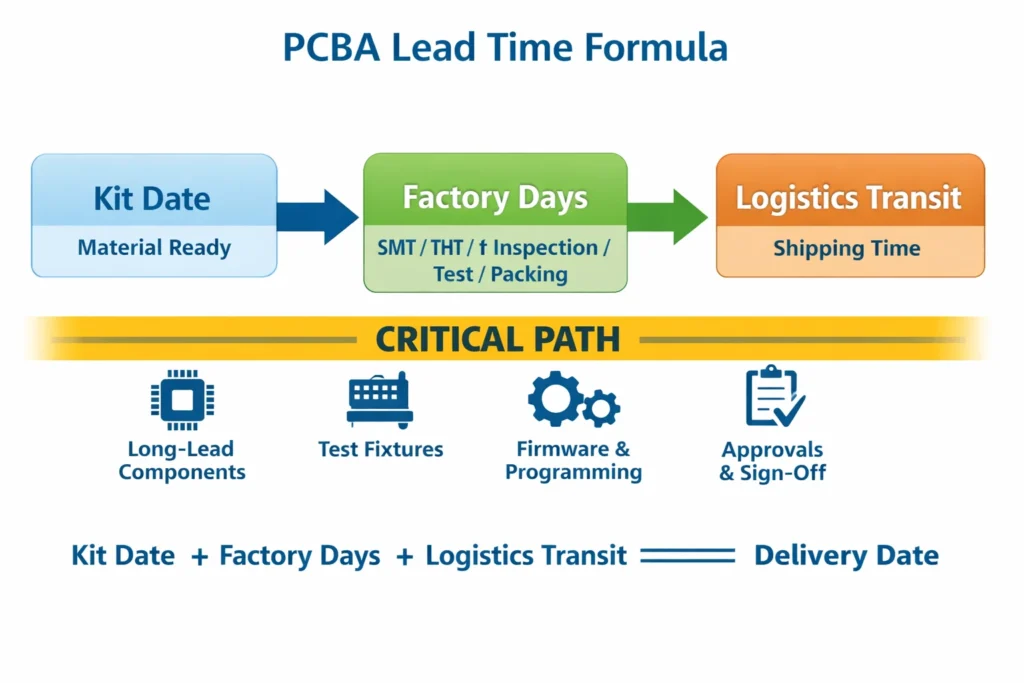
Delivery date = Kit date + (SMT / THT / inspection / test / packing) production cadence + logistics transit time
The critical path typically shows up in:
Long-lead components (key ICs, connectors, custom magnetics, etc.)
Test fixtures (ICT / FCT fixtures)
Firmware / programming files and version confirmation
Customer approval gates (DFM / FAI / test sign-off)
Three Questions to Ask for a Meaningful Lead Time Commitment
When can you achieve “kit complete” (Kit Date)? (Or when can the supplier complete turnkey sourcing?)
How many working days from Kit Date to ready-to-ship? (Line cadence + inspection + test + packing)
Which risks could delay Kit Date or test sign-off? (Supplier should provide a risk list and fallback options)
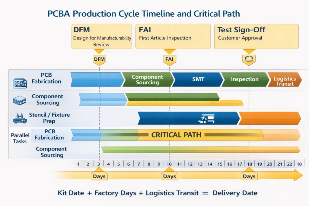
PCBA Production Cycle Breakdown
Stage Breakdown Table
| Stage | Main Output | Key Inputs That Drive Lead Time | Common Bottlenecks | What You Need to Provide in Advance |
|---|---|---|---|---|
| PCB fabrication | Bare boards available | Layer count / thickness / surface finish (ENIG, etc.) | Special processes; impedance/stack-up confirmation | / |
| Component sourcing | Kit complete | BOM accuracy; approved alternates strategy; AVL | Shortages / long lead times / NRND-EOL parts | BOM + alternate rules |
| SMT placement / reflow | SMT completed | XY / footprints / panelization | Changeovers; BGA process window | Gerber + centroid + assembly drawing |
| Inspection | Quality release | Acceptance class (Class 2/3) | Rework loops; X-ray queue | Quality standard + acceptance criteria |
| Testing | Test passed | Fixtures / test procedure / firmware | Fixture not started; unclear firmware version | Test spec + firmware + version rules |
| Packing / documents / shipment | Ready to ship | ESD/MSL/labels/CoC | Moisture control & reseal; missing documents | Label template + document checklist |
| International logistics | Delivered | Incoterms (EXW/DDP, etc.) | Customs docs; partial shipment strategy | Ship-to address / terms / split-shipment plan |
SMT Placement & Reflow: What Determines Scheduling and Changeover Cost
The “actual manufacturing time” of SMT is often not long. What truly drives lead time is preparation and changeover: programs, fixtures, stencils, material loading, and first-article confirmation.
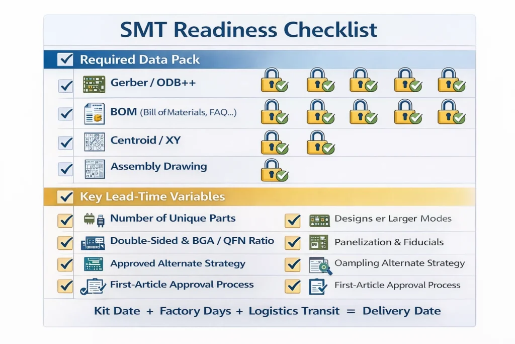
Pre-SMT Preparation
Please ensure the following files are consistent, traceable, and share the same version control:
Gerber or ODB++
BOM (must include manufacturer part number, package, and approved alternates strategy)
Centroid / XY file (including rotation, datum definition)
Assembly drawing + special process notes (polarity, DNP, glue, hand-solder areas)
Five Variables That Determine SMT Lead Time
Number of unique parts: More unique part numbers increase loading and verification time
Double-sided assembly + BGA/QFN ratio: Expands the process window and increases X-ray needs
Panelization method and fiducials/datums: Impacts placement efficiency and yield
Whether alternates are pre-approved: Determines whether shortages can be handled without line stoppage
First-article approval mechanism: Whether FAI requires customer remote/on-site sign-off
How to Avoid Rework Loops
Clearly Define the Adopted Standard and Class
Appearance and assembly acceptability: IPC-A-610 (agree on Class 1/2/3)
Soldering process and workmanship requirements: IPC J-STD-001
AOI and X-ray: Why They Become “Queue Points”
AOI is typically part of the line cadence; however, when false-call rates are high (inconsistent data / unclear polarity definition), time is consumed in review and rework.
X-ray is mandatory for hidden joints such as BGA/LGA. If equipment capacity is limited, multiple orders can create queueing.
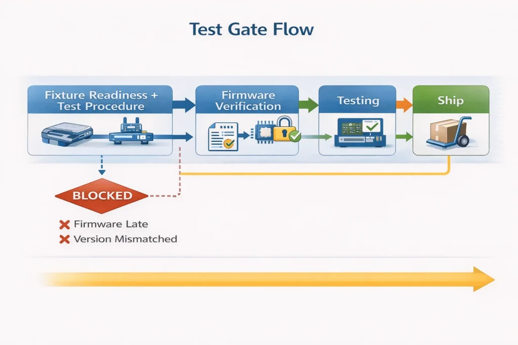
Testing: Fixtures and Firmware Are the Biggest Variables
Selecting the Test Method
Flying probe: Suitable for prototypes / low volume; flexible but limited in coverage and speed
ICT: Better for stable volume; requires a fixture; strong in efficiency and consistency
FCT (functional test): Verifies real operating conditions; often requires customer test procedure and golden unit
Programming / flashing: Common for MCU/FPGA; unclear version management directly blocks shipment
Firmware and Version Control
Please provide at minimum:
Firmware file (bin/hex, etc.) + verification method (hash / version number)
Programming interface and tooling requirements (JTAG / SWD / UART, etc.)
Binding rule (firmware version ↔ part number / serial number)
Packing and International Logistics
ESD: Authoritative References to Align On
ESD control program requirements: IEC 61340-5-1
ESD protective packaging requirements: ANSI/ESD S541
MSL Moisture Control
For MSL handling/packing/shipping/use practices, refer to IPC/JEDEC J-STD-033
Logistics and Terms
Air/express vs sea freight can differ dramatically, and Incoterms (EXW/DDP, etc.) changes customs responsibility and document preparation.
It is recommended to clarify in the schedule: ship date and estimated arrival date are not the same, and provide a customs/document checklist (CoC, packing list, commercial invoice, etc.)
Top 10 Most Common Causes of Delays (and Preventive Actions Engineering/Procurement Can Apply Directly)
BOM missing MPN or unclear package → Prevention: add MPN, package, alternates strategy
Key IC shortage / EOL → Prevention: AVL + pre-approved alternates
Centroid datum inconsistent with Gerber → Prevention: data consistency review
DNP / polarity marking unclear → Prevention: assembly drawing must show polarity and DNP list
Fixture not initiated at quoting stage → Prevention: confirm test method and fixture requirement early
Firmware arrives late or versions are messy → Prevention: version number + checksum + binding rule
BGA requires X-ray but capacity not reserved → Prevention: declare X-ray requirement before order release
MSL floor life exceeded → rebake required → Prevention: manage per IPC/JEDEC J-STD-033
FAI / test sign-off needs customer approval but no gate set → Prevention: define approver, timing, template
Missing labels/documents cause receiving hold → Prevention: standardize document checklist and label template
