Table of Contents
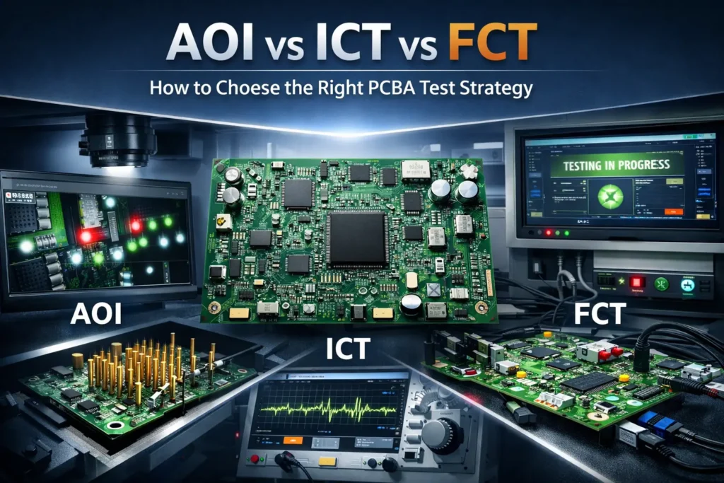
AOI vs ICT vs FCT in PCBA Testing: Which Combination Fits Your Board, Volume, and Risk Level?
When engineers and sourcing teams compare PCB assembly suppliers, they often ask a familiar question:
Do you offer AOI, ICT, or FCT?
But in practice, that is not the most useful question.
A better question is this:
Which defects will your test strategy actually catch before shipment, and which risks could still escape?
That is where AOI, ICT, and FCT need to be separated clearly.
These three methods do not perform the same role. AOI is mainly used to detect visible assembly and soldering defects. ICT verifies electrical integrity at the board level and helps identify structural faults such as opens, shorts, and wrong component values. FCT powers up the board and checks whether it behaves as intended in real operating conditions. In other words, they are complementary, not interchangeable.
For PCB assembly buyers, choosing the wrong test mix can create two problems at the same time. One is under-testing, which increases escape risk, field failures, and warranty cost. The other is over-testing, which adds unnecessary fixture cost, engineering effort, and lead time. The right strategy depends on product complexity, reliability expectations, build quantity, and where the project is in its lifecycle.
This article focuses specifically on AOI vs ICT vs FCT decision-making for PCB assembly projects, rather than giving a broad overview of every possible PCBA test method.
AOI vs ICT vs FCT at a Glance
| Method | What It Best Detects | What It Can Miss | Best Fit | Setup Burden | Speed in Production |
|---|---|---|---|---|---|
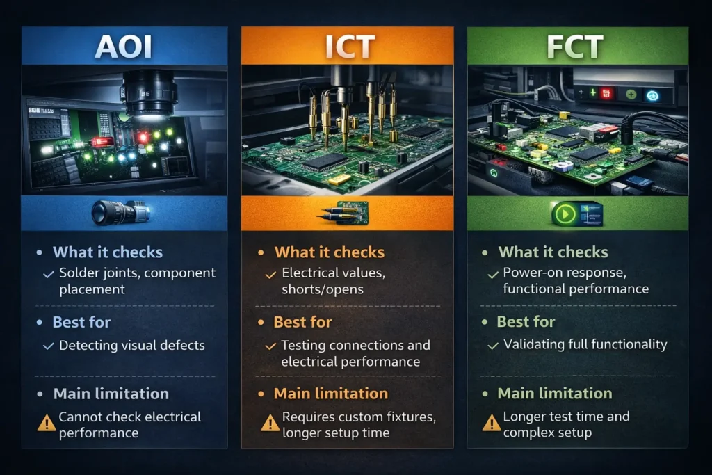
| AOI | Missing parts, polarity errors, solder bridges, tombstoning, visible solder defects | Hidden joint issues, wrong electrical values, firmware and system behavior | Visual process control, first-line screening | Low | Fast |
| ICT | Opens, shorts, wrong values, net-level electrical faults, some assembly-related electrical issues | Firmware logic, interface interaction, full system behavior | Stable designs, repeat builds, mid- to high-volume production | Medium to high | Very fast once fixture is ready |
| FCT | Boot behavior, power-up sequence, firmware execution, communication interfaces, load response | Fine root-cause localization, some latent assembly weaknesses under long-term stress | Boards with MCU, firmware, I/O, or higher functional risk | Medium to high | Moderate |
Why AOI, ICT, and FCT Are Often Confused
Inspection vs. Electrical Test vs. Functional Verification
AOI, ICT, and FCT all belong to the quality assurance process, but they answer different questions.
AOI asks:
Was the board assembled correctly from a visual and soldering perspective?
ICT asks:
Is the board electrically correct at the circuit and interconnect level?
FCT asks:
Does the assembled board actually work as intended when powered on?
That difference matters because PCBA failures do not come from one source only. Some failures begin with visible assembly defects such as missing parts, polarity reversal, or solder bridges. Others come from wrong values, open circuits, or electrical faults that are not obvious visually. Still others only appear when firmware runs, interfaces communicate, or the board operates under load.
Why “The Best Test Method” Depends on Product Risk, Not Just Cost
There is no single best test method for every board.
A simple low-risk control board may not need the same level of test coverage as an industrial controller, an IoT gateway, or a product with complex firmware and communication interfaces. The right decision depends on more than unit cost. It depends on:
- end-use risk
- circuit complexity
- reliability expectations
- production volume
- design maturity
- the cost of failure after shipment
For some products, a lighter test strategy is commercially reasonable. For others, insufficient testing can create a much larger downstream cost than the test itself.
Why This Comparison Matters to Engineers and Procurement Teams
For engineers, test strategy affects design-for-testability, debug speed, and final product quality.
For procurement and supply chain teams, it affects fixture investment, lead time, supplier selection, yield risk, and post-shipment failure cost.
A serious PCB assembly evaluation should not compare factories by assembly price alone. It should also compare:
- defect coverage
- test capability
- reporting depth
- traceability discipline
- readiness to review DFM and DFT issues early
That is where the difference between a basic assembler and a more reliable manufacturing partner becomes visible.
What AOI, ICT, and FCT Actually Verify
What AOI Detects: Placement, Polarity, Solder Appearance, and Visible Defects
AOI, or Automated Optical Inspection, is a visual inspection method. It uses cameras and inspection software to compare the assembled board against expected patterns and parameters.
AOI is strong at detecting visible physical and solder-related defects, including:
- missing components
- wrong or misplaced components
- polarity errors
- tombstoning
- visible solder bridges
- insufficient or excessive solder
- bent leads or obvious alignment issues
Its value is especially high as a first-line screening tool in SMT production. It helps catch common assembly defects early and supports process control before bad boards move further downstream.
AOI can be placed at different points in production depending on the line strategy, such as after paste printing, after placement, or after reflow. In all cases, its main strength is the same: fast, automated detection of visible manufacturing problems.
But AOI is still fundamentally a visual tool. It can only judge what can be inspected optically.
What ICT Detects: Opens, Shorts, Wrong Values, and Assembly-Level Electrical Faults
ICT, or In-Circuit Test, is an electrical structural test. It typically uses a bed-of-nails fixture or another probing method to contact designed test points on the PCB assembly.
ICT is especially good at detecting:
- opens
- shorts
- wrong resistor, capacitor, or inductor values
- wrong orientation of certain devices
- net-level electrical faults
- some assembly-related electrical failures that are not obvious visually
Its biggest advantages are speed, repeatability, and fault localization. Once the fixture and program are ready, ICT can test boards quickly and help identify where the electrical issue is located. That makes it highly valuable for stable repeat production.
However, ICT depends heavily on test-point accessibility and design-for-testability. If the layout does not provide proper probe access, realistic ICT coverage becomes harder to achieve.
What FCT Detects: Power-Up Behavior, Firmware Logic, Interfaces, and Load Conditions
FCT, or Functional Circuit Test, verifies whether the board behaves correctly when powered on in a defined operating setup.
FCT is designed to validate system-level behavior such as:
- power-up and boot sequence
- firmware execution
- logic response
- communication interfaces such as UART, USB, CAN, SPI, or I2C
- input/output behavior
- load response
- application-specific operating functions
This makes FCT the closest of the three methods to real product use.
If a board must boot, communicate, respond through interfaces, regulate power correctly, or perform firmware-driven functions under expected conditions, FCT is the method that confirms those behaviors.
Its value is especially high for boards with MCUs, embedded software, communication modules, sensor systems, or user-facing functions.
What Each Method Cannot Detect—and Why That Matters
Why AOI Cannot Prove Electrical Integrity or End-Use Performance
A board can look correct and still be electrically wrong.
AOI may confirm that a component is present and apparently placed correctly, but it cannot prove that the component value is correct in-circuit, that the electrical path is healthy, or that the board will behave properly once powered on.
It also cannot truly validate:
- wrong passive values that look visually normal
- hidden joint defects under packages
- intermittent electrical issues
- firmware-related failures
- system behavior under load
In short, visually correct does not mean electrically correct or functionally reliable.
Why ICT Cannot Fully Validate Firmware or System-Level Behavior
ICT is excellent for structural electrical checks, but it does not replace true operational testing.
A board can pass ICT and still fail later because of:
- firmware issues
- timing problems
- interface misbehavior
- boot instability
- power sequencing problems
- application-level logic failures
ICT is strongest when the goal is to verify that the assembly is electrically sound before deeper functional testing begins. It is not the same as proving the full product behaves correctly in real use.
Why FCT May Miss Latent Assembly Weaknesses Until Later in Field Use
FCT is very good at answering the question, “Does the board work right now under defined test conditions?”
But that is not always the same as, “Will this board remain reliable over time?”
A borderline solder joint, a micro-crack, or an internal weakness may not fail during a short functional test. It may only fail later after:
- vibration
- thermal cycling
- long-term operation
- repeated on/off use
- environmental stress
That is why FCT, while critical, does not replace every other form of manufacturing control. In higher-reliability products, deeper inspection or reliability screening may still be needed alongside standard AOI, ICT, and FCT.
Common PCBA Defects and Which Test Catches Them Best
Missing Components, Tombstoning, Polarity Errors, and Solder Bridges
These are classic assembly-level defects, and AOI is usually the strongest first-line defense.
It can quickly catch:
- missing parts
- rotated parts
- polarity mistakes
- tombstoning
- obvious solder bridges
- visible solder imbalance
For these defect types, AOI is usually the most efficient first screen.
Opens, Shorts, Wrong Values, and Net-Level Faults
These are electrical defects rather than purely visual ones.
ICT is much better than AOI at detecting:
- open circuits
- short circuits
- wrong passive values
- connectivity faults
- certain electrical failures caused by assembly issues
For prototypes or small-volume builds where fixture-heavy ICT may not be practical, flying probe can sometimes provide part of this role with more flexibility.
Boot Failures, Interface Errors, Load Instability, and Functional Mismatch
These are dynamic, powered, system-level problems.
FCT is the most suitable method for detecting:
- failure to boot
- communication errors
- unstable behavior under load
- incorrect firmware response
- I/O mismatches
- application-level performance issues
These defects often do not appear in AOI or ICT because they are only visible when the board is actually powered and operating.
Defect-to-Test Mapping
| Defect / Risk | AOI | ICT / Flying Probe | FCT | Related Higher-Reliability Methods |
|---|---|---|---|---|
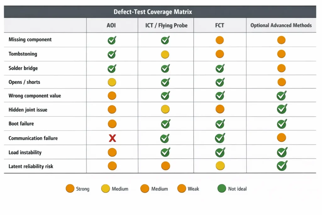
| Missing or reversed parts | Strong | Partial | Weak | Not primary |
| Visible solder bridges / tombstoning | Strong | Partial | Weak | Not primary |
| Opens / shorts / wrong passive values | Weak | Strong | Partial | Not primary |
| Hidden BGA / QFN joint issues | Weak | Partial | Weak | X-ray may be needed |
| Boot / firmware / I/O failures | Weak | Weak | Strong | Not primary |
| Latent reliability risk under stress | Weak | Weak | Partial | Burn-in / ESS may help |
When Is AOI Enough—and When Is It Not?
Low-Complexity Boards with Lower Functional Risk
For some simple, lower-risk boards, AOI plus a basic power-on or limited functional check can be a practical and cost-efficient strategy.
This may apply to boards with:
- simple circuits
- limited logic
- minimal interface complexity
- low functional risk
- lower consequence of failure
That does not make AOI alone universally sufficient. It simply means that for certain low-risk projects, the most economical test mix may not require deep electrical screening.
Boards with MCU, Firmware, Communication Interfaces, or Power Conversion
Once a board includes a microcontroller, firmware, communication interfaces, or complex power behavior, the test requirement changes significantly.
The risk is no longer just visible assembly quality. It includes:
- support circuit integrity around the MCU
- firmware behavior
- interface timing and communication
- reset and boot stability
- power rail performance under dynamic conditions
For these boards, AOI alone is rarely enough. A more robust combination usually includes FCT and often some form of electrical verification such as ICT or flying probe, depending on stage and volume.
Why Higher-Reliability Products Usually Need More Than AOI
Industrial electronics, medical-adjacent electronics, automotive-related assemblies, and other higher-reliability products often need a more layered quality strategy.
That is because they usually face one or more of the following:
- lower tolerance for escapes
- greater use of hidden-joint packages
- higher reliability expectations
- stronger traceability requirements
- more demanding compliance or audit needs
In these cases, AOI may remain essential, but it should not be treated as the only serious control point. A more structured approach may include ICT, FCT, stronger traceability, and in some programs, related inspection or reliability screening methods.
How to Choose the Right Test Strategy by Project Stage
Prototype / NPI: Fast Learning and Basic Risk Screening
At the prototype or NPI stage, the goal is usually fast validation and engineering learning, not maximum test fixture efficiency.
Designs may still change. Firmware may still evolve. Quantities are often low.
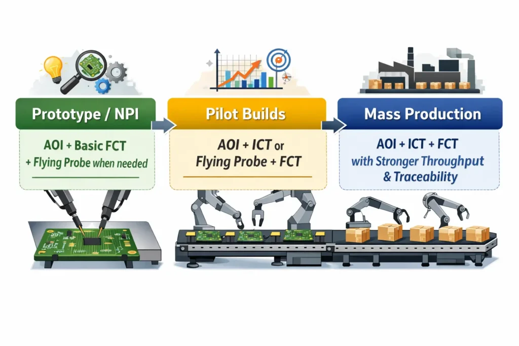
In this phase, a practical strategy is often:
- AOI for visible assembly screening
- FCT or basic functional verification for real behavior
- flying probe where deeper electrical insight is needed without committing to full ICT fixture cost
If the design includes hidden-joint packages or dense layouts, additional inspection support may also be considered early.
Pilot Builds: Stabilizing Yield and Verifying Repeatability
Pilot builds are where testing starts to shift from design validation to process validation.
At this point, the goal is not only to see whether the board works, but also to see whether it can be built consistently.
That is where a stronger combination often becomes useful:
- AOI to control visible process quality
- ICT or flying probe to verify electrical consistency
- FCT to confirm the process is still delivering working boards
This stage is often the best time to refine the long-term production test strategy.
Mass Production: Balancing Coverage, Throughput, and Cost per Unit
In mass production, efficiency becomes a major factor.
The right test mix must balance:
- coverage
- cycle time
- bottleneck risk
- fixture investment
- repair efficiency
- per-unit cost
This is where ICT becomes more attractive for many stable products, because the fixture cost can be spread across larger volumes and the speed advantage becomes more meaningful.
At the same time, FCT still plays an important role for boards that need proof of real operating behavior before shipment.
How Volume Changes the AOI vs ICT vs FCT Decision
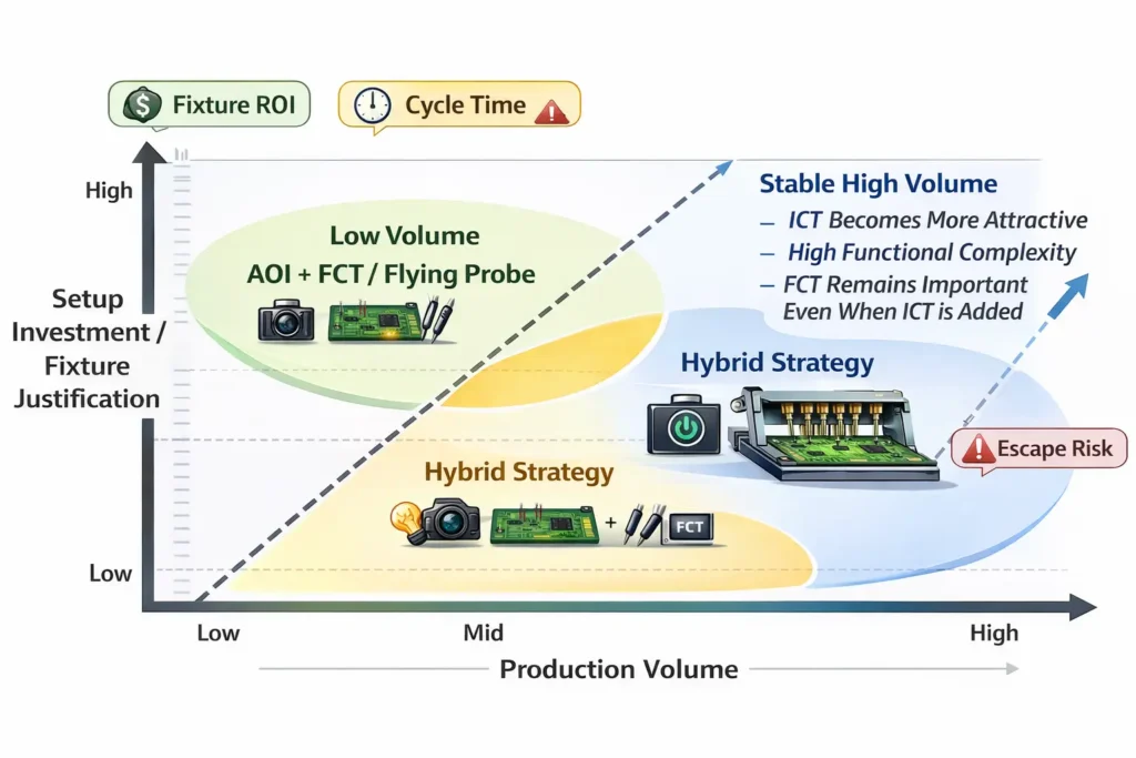
Why ICT Becomes More Attractive in Stable Mid- to High-Volume Production
ICT often becomes more commercially attractive when:
- the design is stable
- volume is predictable
- the fixture cost can be amortized
- fast throughput matters
- precise fault isolation saves repair time
At this point, ICT can improve both efficiency and consistency. It can also reduce the number of electrically bad boards that move downstream into more expensive functional test or final assembly stages.
Why AOI + FCT Is Often a Practical Starting Point for Lower Volumes
For low-volume production, product launch phases, and changing designs, AOI plus FCT is often a practical starting point.
This combination keeps setup lighter while still covering two critical areas:
- visible assembly quality
- real powered behavior
Where deeper electrical insight is needed, flying probe can often provide flexibility without requiring full ICT fixture investment.
How to Think About Fixture ROI, Cycle Time, and Total Cost of Quality
Test strategy should not be judged only by the visible quote line for testing.
A more useful decision framework includes three questions:
Fixture ROI:
Will the fixture investment be justified by expected production volume and repeat use?
Cycle Time Impact:
Will the chosen test step become a production bottleneck, or will it improve flow and defect containment?
Total Cost of Quality:
Does the test plan reduce expensive downstream failures, service returns, and field risk enough to justify the setup cost?
For many buyers, this wider view leads to better decisions than simply trying to minimize test cost at the quotation stage.
Cost and Lead Time Trade-Offs Buyers Should Understand
AOI: Fast to Deploy, Easy to Scale, but Not Deep Enough Alone
AOI is usually fast to introduce and efficient to scale across many builds.
Its strengths include:
- low setup burden
- strong value for common visual defects
- easy integration into SMT process control
- support for fast production screening
Its weakness is depth. AOI alone does not provide enough confidence for many complex or higher-risk boards.
ICT: Higher NRE Up Front, but Excellent Throughput Once the Design Stabilizes
ICT usually requires more up-front work.
That may include:
- fixture development
- test-point planning
- program preparation
- design-for-testability review
But once prepared, it delivers strong throughput and efficient fault isolation, which is why it often makes sense for stable repeat production.
FCT: More Engineering Input, More Setup Time, More Real-World Confidence
FCT usually requires more engineering coordination than AOI.
It may depend on:
- firmware readiness
- interface definitions
- load conditions
- pass/fail criteria
- custom test procedures
- station or fixture design
That setup effort is often worth it because FCT provides the strongest direct evidence that the board behaves as intended in actual use.
What Your PCBA Supplier Needs from You Before ICT or FCT Can Work Well
DFT Basics: Test Points, Access, Connectors, and Probeability
A strong test plan starts with design readiness.
If ICT is expected, the board should support test access. That means buyers and engineers should consider:
- test points
- physical probe access
- connector accessibility
- practical fixture contact strategy
- whether the board is realistically probeable at all
If that work is ignored too early, test coverage becomes harder and more expensive later.
Firmware, Test Procedures, and Pass/Fail Limits
For meaningful FCT, the supplier usually needs more than production files.
They often also need:
- firmware or programming status
- expected outputs
- test procedures
- limits for pass/fail judgment
- definitions of what “functional” means for this specific board
Without that information, FCT becomes vague, inconsistent, or delayed.
Golden Samples, Interface Definitions, and Load Conditions
For smoother test development, buyers should also be ready to provide:
- a golden sample if available
- connector and interface definitions
- load conditions
- expected operating logic
- relevant special handling notes
These details reduce ambiguity and help the supplier build a more practical and reliable test flow.
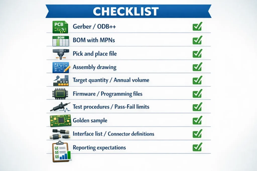
What to Send Your Supplier for Test Planning
| Item | Why It Matters |
|---|---|
| Gerber / ODB++ | Needed for manufacturability review and fixture planning |
| BOM with MPNs | Needed for sourcing control, alternates, and risk review |
| Pick and Place / centroid | Supports assembly validation and test planning |
| Assembly drawing | Clarifies polarity, DNP items, and special notes |
| Target quantity and annual volume | Helps decide whether fixture-heavy ICT is justified |
| Firmware / programming files | Needed for meaningful FCT setup |
| Test procedures / pass-fail limits | Defines what “working” means |
| Golden sample | Helps validate expected behavior |
| Interface list / connector definitions | Supports FCT station design |
| Reporting expectations | Aligns quality records and traceability output |
Need a practical AOI, ICT, or FCT recommendation for your next PCB assembly project?
Send PCBAgroup your Gerber or ODB++, BOM, target volume, firmware status, and test requirements. Our team can review manufacturability and testability, then recommend a practical inspection and test strategy for prototypes, pilot builds, or volume production.
Questions Buyers Should Ask Before Approving a PCBA Test Plan
What Defects Are Screened by AOI, ICT, and FCT in This Project?
Do not stop at asking whether a supplier “has AOI” or “can do FCT.”
Ask instead:
- What specific defects are screened by AOI in this product?
- What electrical faults are covered by ICT or flying probe?
- What functions, interfaces, and operating conditions are verified in FCT?
Capability labels matter less than actual coverage.
What Coverage Is Expected—and Where Are the Gaps?
No test plan covers every possible risk equally.
A strong supplier should be able to explain:
- what the plan is designed to catch
- what remains outside coverage
- whether hidden joints, firmware logic, or stress-related weaknesses need additional control
- whether DFT limitations restrict achievable ICT coverage
This is one of the most important buyer questions because it separates realistic test planning from vague marketing language.
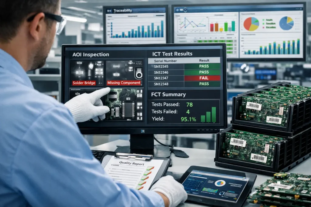
What Reports, Logs, and Traceability Records Will Be Delivered?
Testing is not only about filtering failures. It is also about generating useful manufacturing data.
A more serious PCBA test plan should define what records will be available, such as:
- AOI defect images or classifications
- ICT logs
- FCT records
- batch or serial-level traceability
- pass/fail summaries
- repair or yield feedback if needed
For higher-reliability products, reporting depth and traceability can be just as important as the test step itself.
Recommended Test Combinations for Different Product Types
Simple Control Boards
For simple control boards with lower functional risk, a practical starting point is often:
- AOI
- basic functional or power-on check
If electrical confidence needs to be raised during early builds, flying probe can sometimes be added without moving straight to fixture-heavy ICT.
IoT and Communication Boards
For boards with MCUs, wireless modules, communication interfaces, or tighter logic dependency, a stronger mix is often more suitable:
- AOI
- ICT or flying probe
- FCT
If hidden-joint packages or dense assemblies are involved, more inspection depth may also be considered depending on product risk.
Industrial, Medical-Adjacent, and Higher-Reliability Electronics
For higher-reliability electronics, a layered strategy is usually more appropriate.
A common baseline may include:
- AOI
- ICT
- FCT
Depending on the application, the quality plan may also require stronger traceability, hidden-joint inspection support, or additional reliability screening.
The key principle is simple: the higher the cost of failure, the less reasonable it becomes to rely on a single shallow test layer.
FAQ
Can AOI replace ICT or FCT?
No. AOI is excellent for visible assembly and solder-related defects, but it does not replace electrical verification or powered functional validation.
Is ICT worth it for low-volume or NPI builds?
Sometimes yes, sometimes no. It depends on design stability, expected quantity, available test points, and whether fixture investment is justified. For low-volume or fast-changing projects, flying probe is often considered before full fixture-based ICT.
When should flying probe be used instead of ICT?
Flying probe is often a practical option when volumes are lower, designs are still evolving, or fixture cost is hard to justify. It provides electrical insight with more flexibility, though it is usually slower than production ICT.
Do I need X-ray for BGA or QFN assemblies?
It depends on package type, reliability expectations, and hidden-joint risk. For assemblies where solder joints cannot be adequately evaluated visually, additional hidden-joint inspection may be appropriate.
What should I send my supplier before they plan ICT or FCT?
At minimum, it helps to provide manufacturing files, BOM, target quantity, firmware status, interface details, and any test expectations or pass/fail criteria.

3 回复