Table of Contents
Box Build Assembly for Electronics: PCBA Integration, Testing, and RFQ Checklist
A PCBA is only part of the manufacturing story. Before an electronic product can be installed, shipped, or integrated into a larger system, the board often has to be mounted into an enclosure, connected to cables, loaded with firmware, tested as a complete unit, labeled, documented, and packed for delivery.
That next stage is box build assembly.
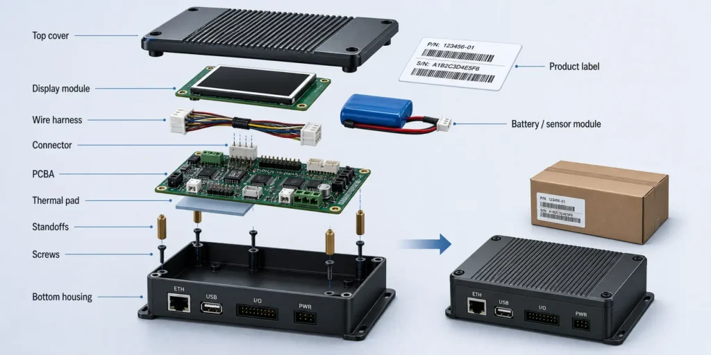
Box build assembly turns a tested printed circuit board assembly into a higher-level electronic module, subassembly, or finished product. The scope can include PCBA installation, mechanical assembly, cable harness connection, display or battery integration, firmware loading, calibration, product-level functional testing, burn-in or reliability testing, serial number labeling, and export packaging.
For engineers and procurement teams, the real question is not only whether a supplier can assemble the PCB. The larger question is whether that supplier can help move the PCBA into a tested, traceable, mechanically integrated, shipment-ready product or module.
This article explains box build assembly from a buyer’s perspective: what it includes, how it differs from PCB assembly and turnkey PCBA, what files belong in a box build RFQ, what should be tested before shipment, what drives cost and lead time, and how to evaluate a box build assembly manufacturer.
Quick Answer: What Is Box Build Assembly?
Box build assembly is the integration of a PCBA with mechanical parts, enclosure hardware, cables, connectors, displays, batteries, sensors, firmware, labels, and packaging to create a complete electronic product or higher-level assembly. It extends beyond board-level PCB assembly into product-level integration, testing, traceability, and delivery preparation.
Simple Definition
In practical terms, box build assembly means taking a tested PCBA and building it into the next level of the product.
That next level may be:
- A finished electronic device
- An industrial control module
- A display and control panel
- A sensor unit
- A power module
- A communication module
- A battery-powered product
- A semi-finished subassembly for system integration
The “box” is not always a literal box. It may be a plastic housing, metal frame, rack, panel, bracket, cabinet, or any mechanical structure that holds the electronics.
What Buyers Usually Mean by "Box Build"
When OEMs, hardware startups, engineers, or purchasing teams search for “box build assembly,” they usually need a manufacturing partner that can take responsibility for more than a populated circuit board.
That scope may include:
- PCB fabrication and PCBA manufacturing
- SMT and through-hole assembly
- Component sourcing or consigned material handling
- PCBA installation into a plastic or metal enclosure
- Cable harness and connector assembly
- Display, battery, sensor, fan, antenna, or power module integration
- Firmware programming and product configuration
- Product-level functional testing
- Calibration or parameter setting
- Burn-in, aging, or reliability testing when required
- Labeling, serialization, barcode control, and packaging
- Final inspection and shipment preparation
The RFQ should define the exact scope. A supplier should not assume that every product needs the same testing depth, documentation package, or final assembly process.
Why Box Build Planning Should Start Before PCBA Production
Many box build problems are created before the first board reaches the assembly line.
Connector position, board outline, mounting holes, keep-out zones, cable exit direction, firmware programming access, test point access, display alignment, heat dissipation, antenna placement, and enclosure clearance all affect final assembly.
When these details are left until after board production, the project may run into:
- Connector interference with the enclosure
- Cable routing that blocks a screw post or fan
- No access to a programming connector after the cover is installed
- Display or LED misalignment with the front panel
- Inaccessible test points for FCT or programming
- Heat sink or thermal pad mismatch
- Wire harness pinching during enclosure closure
- Test fixture redesign after a mechanical change
- Final assembly rework that was invisible at PCBA level
A strong box build project treats electronics, mechanics, firmware, testing, and packaging as one connected manufacturing plan.
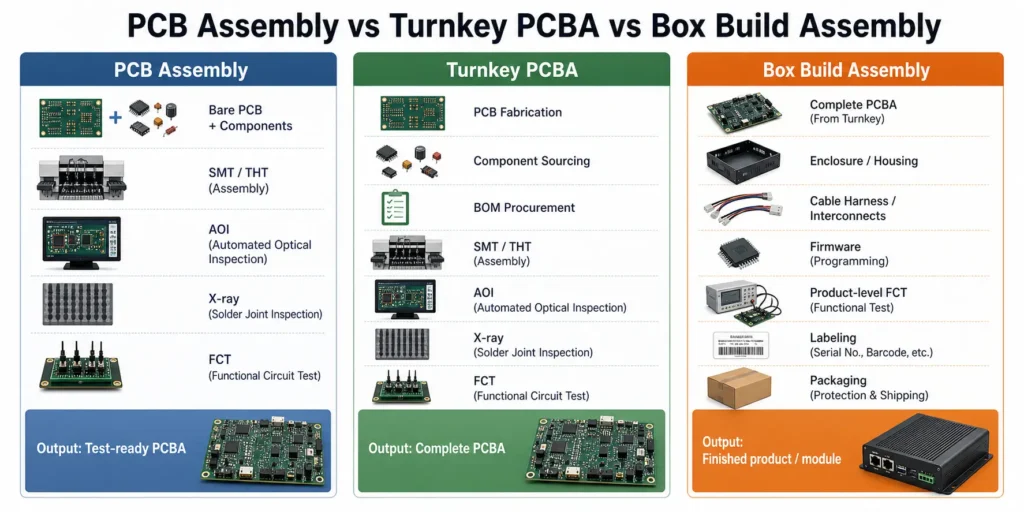
Box Build Assembly vs PCB Assembly vs Turnkey PCBA
Box build assembly is often used alongside terms such as PCB assembly and turnkey PCBA. They are related services, but the manufacturing scope is different.
PCB Assembly
PCB assembly, or PCBA manufacturing, is the process of mounting and soldering electronic components onto a bare printed circuit board.
It may include:
- Solder paste printing
- SPI solder paste inspection
- SMT component placement
- Reflow soldering
- Through-hole insertion
- Wave soldering, selective soldering, or manual soldering
- AOI inspection
- X-ray inspection for hidden solder joints when required
- ICT, flying probe, or functional testing depending on test access and project scope
- Board-level firmware programming when specified
The output is a PCB assembly: a functional or test-ready electronic board.
Turnkey PCBA
Turnkey PCBA adds material responsibility to board-level manufacturing. The supplier handles PCB fabrication, component sourcing, and PCB assembly under one project scope.
In a turnkey project, the buyer normally provides Gerber or ODB++ files, a BOM, centroid data, assembly drawings, testing requirements, and production quantities. The supplier sources the boards and components, assembles the PCBAs, inspects them, tests them according to the agreed plan, and ships the completed boards.
Turnkey PCBA focuses on materials and board-level manufacturing. It does not automatically include enclosure assembly or finished-product integration unless those tasks are included in the RFQ.
Box Build Assembly
Box build assembly starts from the PCBA and moves into product-level integration.
It may include:
- Mounting the PCBA into an enclosure or frame
- Installing displays, batteries, fans, sensors, antennas, switches, or power supplies
- Connecting internal wiring and cable harnesses
- Securing cables with clips, ties, sleeves, or strain relief
- Applying thermal pads, heat sinks, insulation, or shielding
- Loading firmware and verifying the correct version
- Performing product-level functional testing
- Adding serial numbers, product labels, and carton labels
- Packing the unit for shipment
The output is a finished electronic product or higher-level module ready for customer integration, installation, or shipment.
| Scope | Main Responsibility | Typical Output |
|---|---|---|
| PCB fabrication | Build the bare printed circuit board | Bare PCB |
| PCB assembly | Mount and solder components onto the PCB | Tested or test-ready PCBA |
| Turnkey PCBA | Source PCB and components, then assemble the board | Complete PCBA with supplier-managed materials |
| Box build assembly | Integrate PCBA with enclosure, cables, firmware, test, labels, and packaging | Finished product or higher-level subassembly |
What Is Included in an Electronics Box Build Project?
A box build project can be very simple or highly involved. One project may only require installing a PCBA into a housing and connecting one harness. Another may require multiple PCBAs, displays, batteries, power supplies, wireless modules, firmware, calibration, data logging, custom test fixtures, and export packaging.
The first rule is to define the scope before quotation.
PCBA Installation and Mechanical Mounting
PCBA installation is the physical mounting of the assembled board into the product structure.
This may involve:
- Screws and standoffs
- Plastic clips
- Metal brackets
- Spacers and washers
- Insulation films
- Thermal pads or thermal grease
- Heat sinks
- Grounding screws
- EMI shielding
- Adhesive, staking, or mechanical locking features
Buyers should define screw type, screw length, torque requirements, grounding points, clearance limits, insulation needs, and cosmetic or mechanical acceptance criteria.
These details matter. The wrong screw length can damage the enclosure. A missing insulating washer can create a short risk. A poorly supported board may pass factory testing but become unreliable after vibration, shipping, or installation stress.
Enclosure and Mechanical Interface Requirements
The enclosure is more than a container. It affects connector access, thermal behavior, EMI performance, serviceability, sealing, and user experience.
Useful mechanical details include:
- 3D STEP file
- 2D mechanical drawing
- Exploded assembly view
- Material and surface finish
- Critical tolerance zones
- Display window dimensions
- Connector opening positions
- Cable exit direction
- Gasket or sealing requirement
- Heat sink or airflow path
- Label position
- Packaging dimensions
If the enclosure is custom, clarify whether the buyer supplies it, the box build supplier sources it, or a third-party mechanical supplier provides it.
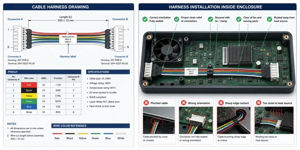
Cable Harness and Connector Assembly
Cables are a frequent source of box build defects because they combine electrical design, mechanical routing, and manual assembly.
A box build project may include:
- Wire harnesses
- Ribbon cables
- FFC or FPC cables
- JST, Molex, TE, Phoenix, or similar connector systems
- Coaxial cables and antennas
- Power leads
- Sensor cables
- Panel-mount connectors
- Switch, LED, fan, or motor wiring
For each cable, define:
- Connector manufacturer part number
- Pinout
- Wire gauge, such as AWG size
- Wire color
- Cable length and tolerance
- Shielding or grounding requirement
- Crimping or soldering requirement
- Connector locking direction
- Labeling rule
- Routing path
- Bend radius
- Strain relief or pull force requirement if applicable
A cable can be electrically correct and still fail in the product if it is routed near a sharp edge, pinched under a cover, pulled too tightly, installed backwards, or left without strain relief.
Display, Battery, Sensor, and Module Integration
Many electronic products are not built around a single board. Box build assembly may involve functional modules such as:
- LCD, OLED, TFT, or touch displays
- FFC or FPC display cables
- Keypads or membrane switches
- LED light pipes
- Rechargeable or primary batteries
- Battery holders or battery packs
- Battery management system connections
- Temperature, pressure, optical, motion, or current sensors
- Wi-Fi, Bluetooth, LoRa, cellular, or RF modules
- Motors, fans, pumps, speakers, or relays
- Power supplies, adapters, or DC input modules
These parts affect test coverage, current draw, thermal design, firmware behavior, mechanical fit, and final inspection.
A wireless module may need antenna placement review. A battery-powered product may need charge and discharge checks. A display product may need alignment, brightness, dead-pixel, color, and touch-response criteria. A sensor module may need calibration and a defined record format.
Labeling, Serialization, and Packaging
Box build assembly often includes final shipment preparation.
This may include:
- Product labels
- Rating labels
- Warning labels
- Serial number labels
- Barcode or QR code labels
- MAC address labels
- Firmware version labels
- Carton labels
- Accessory packing
- ESD bags
- Foam inserts
- Trays
- Retail boxes
- Export cartons
For export buyers, labeling and packaging should be controlled early. A wrong barcode, unreadable serial number, missing accessory, weak foam insert, or incorrect carton label can delay shipment even when the product passes testing.
Typical Box Build Assembly Process
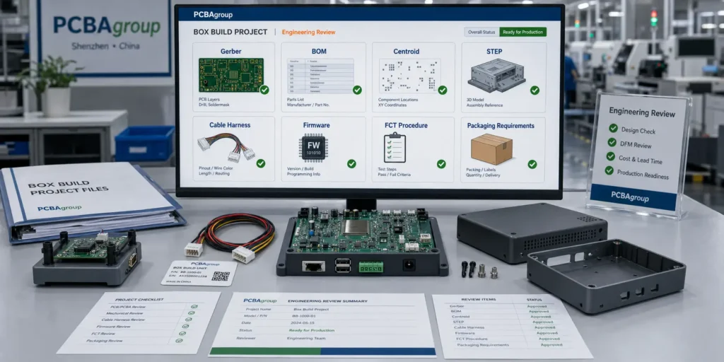
A controlled box build process connects engineering review, material inspection, PCBA manufacturing, mechanical integration, firmware programming, product-level testing, final inspection, and packaging.
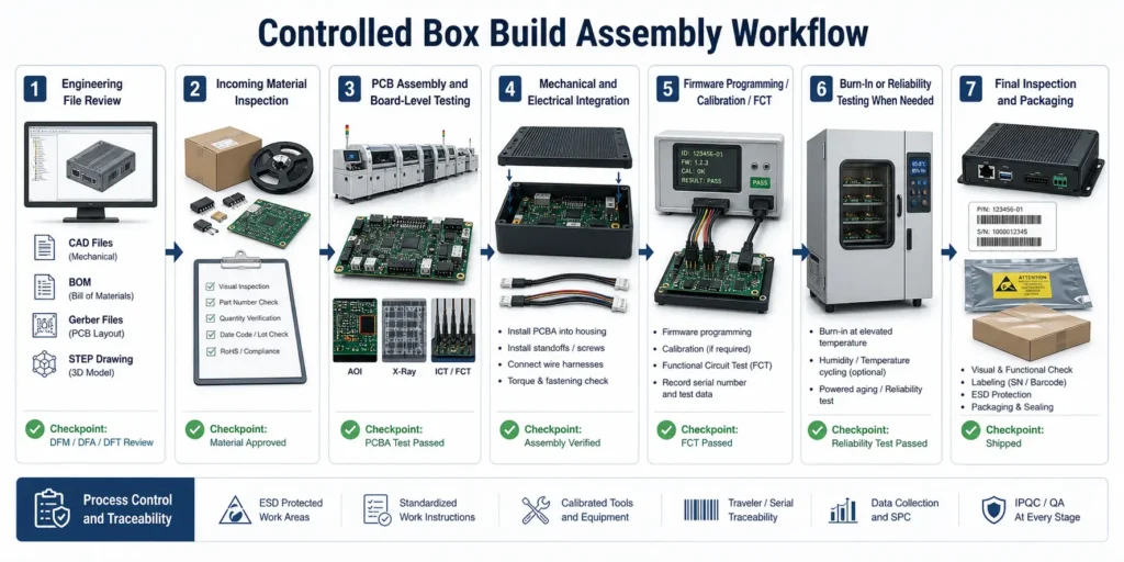
Step 1 - Engineering File Review
Before material purchasing or production, the supplier should review the technical package for completeness and consistency.
This may include:
- Gerber or ODB++ files
- BOM with manufacturer part numbers
- Centroid or pick-and-place file
- Assembly drawings
- Schematics when needed
- 3D STEP files
- 2D mechanical drawings
- Enclosure drawings
- Cable harness drawings
- Firmware files
- Programming instructions
- Test procedures
- Packaging instructions
- Quality and traceability requirements
The purpose is to find risks while they are still inexpensive to correct.
Typical review questions include:
- Do the BOM, Gerber, centroid, and drawings belong to the same revision?
- Does the PCBA fit the enclosure?
- Are connector openings aligned?
- Are tall components close to the lid?
- Can the programming interface be accessed after assembly?
- Are test points accessible for FCT or ICT?
- Are cable lengths and pinouts defined?
- Are burn-in, calibration, or reporting requirements included?
- Is the enclosure customer-supplied or supplier-sourced?
This is where DFM, DFA, and DFT thinking should begin.
Step 2 - Incoming Material Inspection
Box build projects involve more material categories than board-only PCBA projects.
Incoming inspection may cover:
- Bare PCBs
- Electronic components
- Customer-supplied parts
- Enclosures
- Cable harnesses
- Connectors
- Screws and fasteners
- Labels
- Batteries
- Displays
- Packaging materials
- Power adapters
- Mechanical parts
Inspection should verify quantity, part number, revision, package labeling, visual condition, critical dimensions when needed, and whether materials match the approved file set.
For consigned or partial-turnkey projects, customer-supplied parts should be clearly separated, labeled, counted, and tracked. Shortage responsibility and attrition allowance should be agreed before production starts.
Step 3 - PCB Assembly and Board-Level Testing
The PCBA should usually be built and checked before final product integration.
Depending on the board design and project scope, PCBA manufacturing may include:
- IQC incoming material inspection
- Solder paste printing
- SPI solder paste inspection
- SMT pick-and-place
- Reflow soldering
- AOI inspection
- X-ray inspection for BGA, QFN, CSP, LGA, or other hidden-joint packages when required
- Through-hole insertion
- Wave soldering, selective soldering, or manual soldering
- First article inspection
- ICT, flying probe, or functional testing depending on test access, volume, and test plan
- Firmware programming when specified
For PCBAgroup, existing site content describes support for PCB fabrication and PCB assembly projects, including SMT assembly, through-hole assembly, SPI, online AOI, offline AOI, X-ray inspection, functional testing, and MES-based traceability. The project-specific scope should still be confirmed during RFQ review.
Step 4 - Mechanical and Electrical Integration
After board-level checks, the assembly moves into mechanical and electrical integration.
This may include:
- Installing the PCBA into the enclosure
- Securing screws to the specified torque
- Applying thermal pads or heat sinks
- Connecting cable harnesses
- Installing displays, batteries, sensors, fans, antennas, or power modules
- Adding gaskets, shields, insulation, or brackets
- Routing cables with clips, ties, or adhesive mounts
- Checking connector orientation and lock engagement
- Closing the enclosure without cable pinching
This stage should follow controlled work instructions. Photos, torque values, cable routing diagrams, inspection points, and rework rules help reduce operator variation.
Step 5 - Firmware Programming, Calibration, and Product-Level Testing
Some products are programmed at board level. Others are programmed after enclosure assembly. The right sequence depends on connector access, test flow, and product design.
Programming may use:
- SWD
- JTAG
- UART
- USB
- ISP connector
- Dedicated programming fixture
- Customer-supplied software tool
Product-level testing may include:
- Power-on check
- Input current measurement
- Output voltage verification
- Firmware version check
- Communication test such as USB, Ethernet, RS-232, RS-485, CAN, Wi-Fi, Bluetooth, or RF
- Button, keypad, or touch panel test
- Display test
- Sensor response test
- Relay, motor, fan, pump, or actuator operation
- Battery charging or discharge check
- Calibration of sensors, power levels, or analog outputs
- Data logging or serial number linking
A useful FCT procedure defines the sequence, fixture, cables, software, load condition, measurement limits, pass/fail criteria, and record format.
Step 6 - Burn-In, Aging, or Reliability Testing When Needed
Not every box build project needs burn-in or environmental testing. These tests should be selected based on product risk, operating environment, customer requirements, and field failure cost.
Possible reliability-related tests include:
- Burn-in or powered aging
- Power cycling
- Temperature and humidity testing
- Thermal cycling
- Vibration or simulated transportation testing
- Salt spray testing for corrosion risk
- Battery charge/discharge testing
- Load testing for power products
PCBAgroup’s existing reliability-focused content mentions support that may include temperature and humidity testing, simulated transportation vibration testing, salt spray testing, and battery testing depending on project requirements. The exact test plan should be agreed before production.
Step 7 - Final Inspection and Packaging
Final inspection confirms that the product is complete, correct, clean, functional, labeled, and ready for shipment.
Typical checks include:
- Correct product version
- Correct enclosure
- No missing screws or brackets
- No loose connectors
- No cable damage or pinching
- Correct firmware version if required
- Correct serial number, barcode, or MAC address label
- Cosmetic condition
- Accessory completeness
- Test record completion
- Packaging method
- Carton label accuracy
Packaging should protect against ESD, vibration, compression, moisture, and handling damage during international shipment.
What Files Should Buyers Provide for a Box Build RFQ?
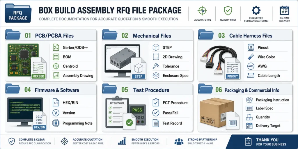
A box build RFQ needs more than a standard PCBA file package. If the supplier receives only Gerber files and a BOM, it may quote the board assembly but miss the mechanical integration, firmware, testing, packaging, and documentation work.
PCB and PCBA Files
Provide the core PCBA files:
| File | What It Should Include | Why It Matters |
|---|---|---|
| Gerber or ODB++ | Copper, solder mask, silkscreen, paste, drill, outline | Defines PCB fabrication and assembly preparation |
| BOM | Ref Des, quantity, MPN, manufacturer, package, DNP, alternates | Supports sourcing, cost review, and material risk checking |
| Centroid file | X/Y coordinates, rotation, side, package | Supports SMT programming and placement review |
| Assembly drawing | Component location, polarity, pin 1, orientation, DNP notes | Reduces placement and manual assembly errors |
| Schematic if available | Circuit context and troubleshooting support | Helps test planning and failure analysis |
| Test point information | ICT, flying probe, programming, FCT access | Supports fixture and test planning |
| Firmware file | HEX, BIN, image file, or customer tool package | Required when programming is in scope |
All files should belong to the same hardware revision.
Mechanical Files
Mechanical files are essential for box build assembly.
Provide:
- 3D STEP file
- 2D enclosure drawing
- Exploded assembly view if available
- Screw and fastener specification
- Torque requirements
- Mounting hardware details
- Thermal pad or heat sink instructions
- Gasket or sealing information
- Display window and connector opening dimensions
- Cosmetic acceptance criteria
- Label placement drawing
- Packaging drawing if available
If there are controlled dimensions, mark them clearly. If the enclosure must not contact the PCBA in certain areas, include keep-out notes.
Cable Harness and Wiring Documents
Cable information should be specific enough for manufacturing and inspection.
Provide:
- Wiring diagram
- Cable harness drawing
- Connector manufacturer part numbers
- Pinout table
- Wire gauge
- Wire color
- Cable length and tolerance
- Shielding or grounding notes
- Crimping, soldering, or terminal requirement
- Routing path
- Labeling requirement
- Pull test or strain relief requirement if applicable
A photo of a sample can help clarify intent, but it should not replace controlled drawings for repeat production.
Firmware, Software, and Configuration Files
If programming or configuration is required, define:
- Firmware file name and version
- Hardware revision compatibility
- Programming interface, such as SWD, JTAG, UART, USB, or ISP
- Programming tool or software
- Encryption or locking requirement
- Verification method
- Default configuration
- Serial number or MAC address writing rule
- Whether the firmware is loaded before or after final assembly
Firmware ambiguity is a common cause of box build delays. The supplier should know exactly which version belongs to each build revision.
Test Procedure and Acceptance Criteria
Product-level testing is difficult to quote without a clear procedure.
Provide:
- Test sequence
- Power input and current limit
- Load condition
- Fixture or cable requirement
- Required software or driver
- Communication interface
- Measurement points
- Calibration method if needed
- Pass/fail limits
- Data logging requirement
- Report format
- Failure handling rule
Instead of writing “functional test required,” state what the technician should do and what result should pass.
| Test Item | Example Acceptance Criteria |
|---|---|
| 3.3 V rail | 3.3 V +/- 5 percent under defined load |
| Ethernet | Link detected and communication packet returned |
| Display | No missing segments, correct test pattern, no visible cable looseness |
| Battery charge | Charge current within defined range and no abnormal temperature rise |
| Sensor | Output within specified tolerance under test condition |
Box Build Testing: What Should Be Verified Before Shipment?
Box build testing verifies the integrated product or module, not only the bare PCBA.
Visual and Mechanical Inspection
Visual and mechanical inspection checks whether the unit was assembled correctly.
Common checks include:
- Correct enclosure and product version
- Correct screw type and quantity
- Fasteners tightened according to work instruction
- No stripped thread or damaged post
- Cable routed correctly
- No cable pinching or sharp-edge contact
- Connector fully seated and locked
- Display aligned with window
- Label placed correctly
- No scratches, dents, contamination, or cosmetic defects beyond agreed criteria
- Accessories included
For products shipped directly to distributors, installers, or end customers, this stage has direct brand impact.
Electrical Safety and Power-On Checks
Before full functional testing, the supplier may perform basic electrical checks.
These may include:
- Short-circuit check between power and ground
- Input polarity check
- Ground continuity check
- Insulation resistance check when required
- Power-on current check
- Output voltage check
- Abnormal heat check
- Battery connection check
- Protection circuit check
For high-current, battery-powered, medical-adjacent, or industrial control products, these checks should be defined clearly in the RFQ.
Functional Testing
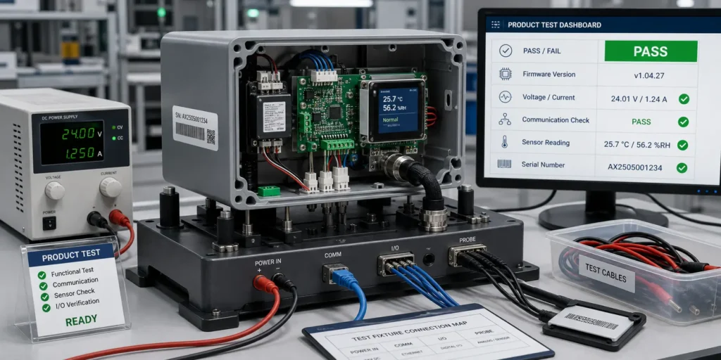
Functional testing verifies whether the assembled product behaves correctly under defined conditions.
Depending on the product, FCT may include:
- Button, switch, or touchscreen test
- LED and display test
- USB, Ethernet, RS-232, RS-485, CAN, wireless, or other communication test
- Sensor response test
- Relay, motor, fan, pump, or actuator operation
- Analog input/output test
- Digital input/output test
- Battery charging and discharge behavior
- Firmware command test
- Serial number, MAC address, or product configuration verification
Functional testing should be defined in a test procedure. It may be performed on every unit, sample-based, or validation-only depending on project risk and agreement.
Burn-In, Aging, and Reliability Testing
Burn-in, aging, or reliability testing can help reveal early-life or environment-related failures, but they should be selected with a specific risk in mind.
Useful test planning questions include:
- Will the product run continuously?
- Will it face heat, humidity, vibration, salt mist, or condensation?
- Does it contain high-current circuits, batteries, relays, motors, or power supplies?
- Is field repair expensive?
- Does the customer require a specific test condition or report?
- Should the test be performed on every unit or on samples?
- What result counts as failure?
For example, a factory control module may benefit from FCT, limited burn-in, and traceability records. An outdoor IoT product may need humidity, condensation, cleaning, coating, and corrosion-risk review. A sealed indoor product with low field failure cost may not need expensive environmental testing.
Quality Control and Traceability in Box Build Assembly
Traceability is one of the major differences between a professional electronics manufacturing partner and a basic assembler.
When a field issue appears, traceability helps answer which batch, material lot, firmware version, test result, and finished units may be affected.
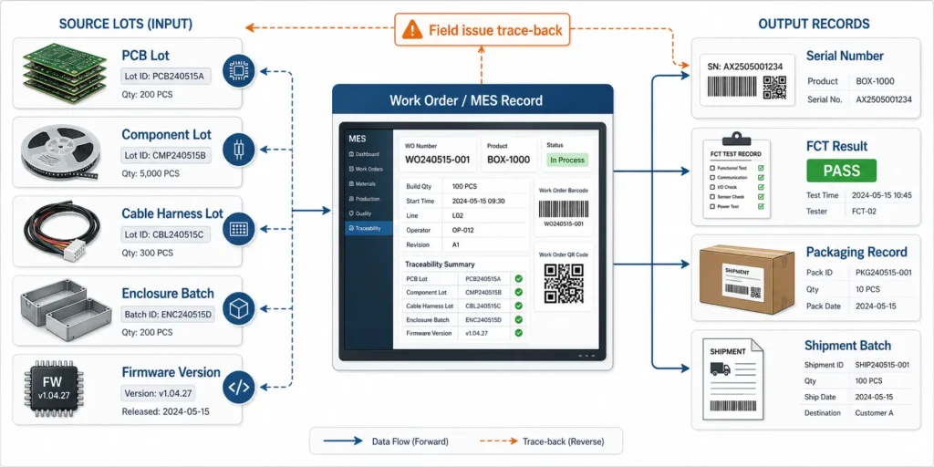
Material Traceability
Material traceability may cover:
- PCB lot
- Component lot
- Critical IC date code
- Enclosure batch
- Cable harness lot
- Battery batch
- Display batch
- Label batch
- Customer-supplied material record
- Packaging material lot when required
Not every project needs the same level of traceability. The requirement should match product risk, customer expectations, and regulatory or contract requirements.
Process Traceability
Process traceability records what happened during manufacturing.
Useful records may include:
- Work order number
- PCB revision
- BOM revision
- Firmware version
- Assembly station
- Operator or line information
- Inspection result
- FCT result
- Burn-in result if required
- Rework record
- Serial number
- Packing record
Mature manufacturing systems may use MES to link material lots, process steps, operators, inspection data, test results, and finished-unit serial numbers.
Common Defects Box Build QC Should Catch
Box build QC should catch defects that may not be visible at PCBA level.
Examples include:
- Connector plugged into the wrong port
- Connector not fully seated
- Cable pinched under a screw or cover
- Cable routed across a heat source or moving part
- Wrong screw length
- Missing grounding screw
- Missing bracket or spacer
- Display misalignment
- Battery connector reversed
- Wrong firmware version
- Duplicate or unreadable serial number
- Incorrect MAC address label
- Missing accessory
- Packaging error
These small integration issues can turn a working PCBA into a failed finished product.
What Affects Box Build Assembly Cost and Lead Time?
Box build cost is not determined by PCBA cost alone. It depends on part count, manual assembly time, enclosure complexity, cable harness work, fixture needs, test duration, documentation, packaging, and material responsibility.
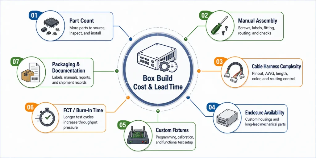
Number of Parts and Manual Assembly Steps
Every additional part adds handling, inspection, and error-prevention work.
Cost may increase with:
- Multiple PCBAs
- Many connectors
- Complex wire harnesses
- Manual screw assembly
- Tight enclosure fit
- Fragile displays
- Adhesives or curing steps
- Gaskets or seals
- Thermal pads and heat sinks
- Cosmetic handling requirements
Designing for assembly helps. Fewer screw types, fewer cable variants, keyed connectors, clear polarity marks, and repeatable routing can reduce both labor time and defect risk.
Custom Fixtures and Functional Test Setup
Testing can be a major cost driver.
Box build testing may require:
- Programming fixture
- Functional test fixture
- Product cradle
- Custom cables
- Load board
- Power supplies
- Communication adapters
- Software tools
- Data logging system
- Golden sample
- Calibration equipment
Some costs are one-time NRE costs. Others repeat with each unit because they add operator time. A 2-minute power-on test and a 30-minute automated FCT with data logging have very different cost and schedule impact.
Enclosure, Cable, and Long-Lead Materials
In box build projects, the bottleneck is not always the PCBA.
Lead time can be affected by:
- Custom plastic enclosure tooling
- Injection-molded or machined mechanical parts
- Sheet metal fabrication
- Cable harness production
- Display availability
- Battery availability
- Power adapter availability
- Label and packaging material lead time
- Customer-supplied parts arriving late
If the enclosure or cable harness is not ready when the PCBAs are complete, final assembly cannot proceed.
Packaging, Documentation, and Compliance Support
Packaging and documentation can also affect cost and lead time.
Examples include:
- Individual packaging
- Custom foam inserts
- ESD protection
- Drop-test packaging
- User manuals
- Accessory kits
- Carton labels
- Barcode serialization
- Inspection reports
- Test reports
- Traceability reports
- Customer-specific documentation
Compliance-related marks and certifications, such as CE, FCC, UL, or medical-device requirements, should be handled carefully. A box build supplier may support manufacturing, documentation, sample preparation, or production controls, but certification responsibility and third-party testing scope should be clearly defined by the buyer and relevant certification body.
Common Mistakes That Delay Box Build Projects
Most box build delays come from incomplete documentation, late firmware, unclear cables, mechanical changes, or undefined testing.
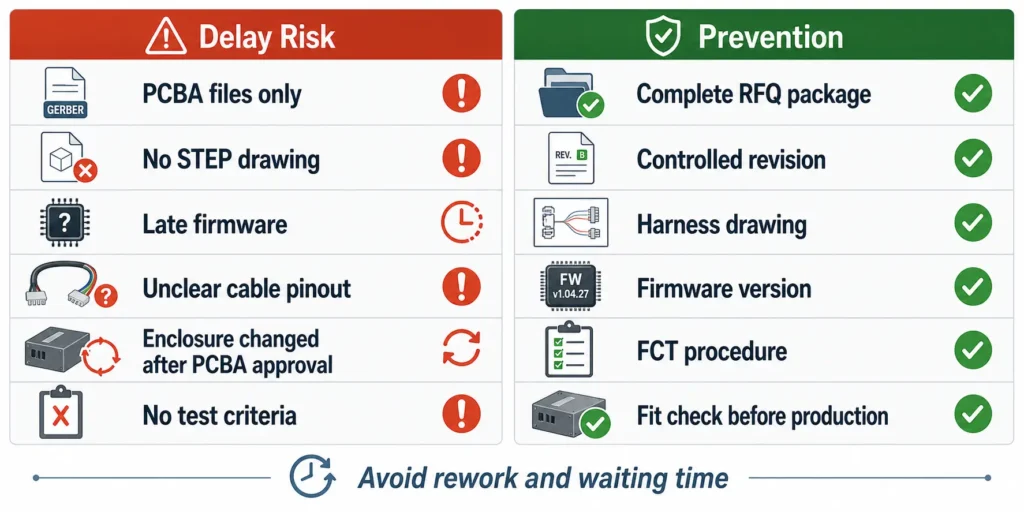
Sending PCBA Files Without Mechanical Drawings
Gerber, BOM, and centroid files are not enough for a box build quote.
Without mechanical drawings, the supplier may not know:
- How the PCBA mounts
- Which screws or brackets are required
- Where cables should route
- Whether connectors align with the enclosure
- Whether tall components touch the lid
- Where labels should be placed
- Whether the product can fit into the test fixture
Mechanical files should be sent with the RFQ, not after PCBA production.
Missing Firmware or Test Instructions
Firmware and testing are frequent bottlenecks.
Delays happen when:
- Firmware is not released before production
- The supplier does not know which firmware version to load
- Programming access is blocked after enclosure assembly
- The test procedure is missing
- Pass/fail criteria are not defined
- Test software or drivers are not provided
- The buyer expects the supplier to develop a fixture without quoting it
If firmware or test requirements are still under development, tell the supplier early. The production plan can then include open items and realistic timing.
Unclear Cable and Connector Requirements
A short note like “connect J1 to J2” is not enough for repeatable box build assembly.
The supplier needs:
- Connector part numbers
- Pinout table
- Wire length
- Wire gauge
- Wire color
- Shielding requirement
- Crimping or soldering requirement
- Cable routing path
- Label rule
- Orientation or locking direction
Controlled harness drawings reduce rework, especially when the product moves from prototype to pilot run or mass production.
Changing the Enclosure After PCBA Approval
An enclosure change can affect the entire product.
Even a small mechanical change may affect:
- Connector alignment
- Cable routing
- Heat sink contact
- Antenna location
- Screw positions
- Display alignment
- Test fixture design
- Packaging dimensions
- Final inspection criteria
If the enclosure changes after PCBA approval, the supplier should re-check mechanical fit, assembly sequence, fixture access, thermal risk, and cable routing before production continues.
How to Choose a Box Build Assembly Manufacturer
A box build supplier should function as a production engineering partner, not just a service provider. The work connects electronics, mechanics, sourcing, testing, and documentation.
Engineering Review Capability
A qualified supplier should ask specific questions before quoting.
Look for feedback on:
- DFM, DFA, and DFT risks
- Mechanical interference
- Connector and cable orientation
- Test access
- Fixture requirements
- Firmware programming method
- Sourcing and long-lead items
- Customer-supplied material handling
- Special processes such as coating, potting, or burn-in
- Revision control
If a supplier quotes a complex box build without engineering questions, the quote is probably built on assumptions.
PCB Assembly and Final Assembly Under One Roof
When PCBA manufacturing and box build assembly are coordinated under one workflow, several risks can be reduced.
Benefits may include:
- Fewer supplier handoffs
- Clearer ownership
- Faster engineering feedback
- Better coordination between board-level test and product-level test
- Easier failure analysis
- Better revision control
- Less communication burden for overseas buyers
This is especially valuable when the product includes firmware, custom cables, mechanical fit risk, or recurring production.
Testing, Traceability, and Communication
Before choosing a supplier, ask:
- Which tests are performed at board level?
- Which tests are performed after final assembly?
- Is FCT performed on every unit, sampled, or validation-only?
- How are test results recorded?
- Can test data be linked to serial numbers?
- How is firmware version controlled?
- How are rework and failures documented?
- How are customer-supplied parts tracked?
- How are revision changes released to production?
- Who handles technical communication in English?
The best supplier is not always the one with the lowest unit price. It is the supplier that reduces total project uncertainty.
How PCBAgroup Supports Box Build Assembly Projects
PCBAgroup is a PCB manufacturing and PCB assembly factory based in Shenzhen, China. Based on existing PCBAgroup site content, the company supports PCB fabrication, component sourcing, SMT assembly, through-hole assembly, inspection, testing, and quality-control processes for export customers.
For box build assembly projects, the exact scope should be reviewed during RFQ because product-level integration varies widely from one project to another.
From PCB Fabrication to PCBA and Product-Level Assembly
Depending on project requirements, PCBAgroup can support or review:
- PCB fabrication
- Component sourcing
- SMT assembly
- Through-hole assembly
- Mixed assembly
- SPI solder paste inspection
- AOI inspection
- X-ray inspection when required
- First article inspection
- Functional testing
- Firmware programming support
- Cable and connector integration
- Enclosure assembly
- Labeling and packaging
- MES-based production traceability
The exact test plan, box build steps, documentation, and acceptance criteria should be confirmed before production.
Suitable Project Types
Box build assembly is often useful for:
- Industrial control products
- IoT devices
- Smart hardware
- Sensor modules
- Power electronics
- Battery-powered products
- Medical-adjacent electronic modules
- Communication devices
- Consumer electronics
- Display and control panels
- Equipment subassemblies
For medical, automotive, or other regulated applications, buyers should define customer standards, documentation requirements, and certification responsibilities clearly during RFQ review.
What to Send PCBAgroup for Review
For a useful box build review, send:
- Gerber or ODB++ files
- BOM with manufacturer part numbers
- Centroid file
- Assembly drawing
- 3D STEP file
- 2D enclosure drawing
- Cable harness drawing
- Firmware file if programming is required
- Programming instructions
- Functional test procedure
- Product photos or golden sample if available
- Packaging and labeling requirements
- Target quantity and quote breaks
- Target lead time
- Sourcing model: turnkey, consigned, or partial turnkey
- Quality and traceability requirements
The goal is to review the project from both PCBA and final assembly perspectives before quotation.
Box Build Assembly RFQ Checklist
Use this checklist before sending a box build RFQ to a manufacturer.
Engineering Files
- Gerber or ODB++ files
- BOM with MPNs and approved alternates
- Centroid or pick-and-place file
- Assembly drawing
- Schematic if available
- Fabrication drawing
- 3D STEP file
- 2D mechanical drawing
- Enclosure drawing
- Cable harness drawing
- Label drawing
- Firmware file
- Programming instructions
- Test procedure
- Packaging instruction
- Revision history
Commercial Information
- Prototype quantity
- Pilot run quantity
- Mass production quantity
- Annual forecast if available
- Quote breaks
- Target lead time
- Shipping destination
- Incoterms if known
- Turnkey, consigned, or partial-turnkey model
- Customer-supplied material list
- Enclosure sourcing responsibility
- Test fixture responsibility
- Packaging preference
- Required documentation
Quality Requirements
- IPC class or workmanship standard
- Board-level inspection requirement
- Product-level functional test requirement
- Firmware verification requirement
- Serial number rule
- Traceability requirement
- Burn-in or aging requirement if needed
- Environmental or reliability testing if needed
- Cosmetic acceptance criteria
- Test report format
- Failure handling process
FAQ
What is box build assembly in electronics manufacturing?
Box build assembly is the process of integrating a PCBA with mechanical parts, enclosure hardware, cables, connectors, firmware, labels, and packaging to create a finished electronic product or higher-level module.
Is box build assembly the same as PCB assembly?
No. PCB assembly focuses on mounting and soldering components onto a printed circuit board. Box build assembly includes additional steps such as enclosure integration, cable connection, firmware programming, product-level testing, labeling, and packaging.
What files are needed for a box build assembly quote?
For a box build quote, provide Gerber or ODB++ files, BOM, centroid file, assembly drawings, STEP files, enclosure drawings, wiring diagrams, cable harness drawings, firmware, test procedure, acceptance criteria, packaging requirements, quantity, and target lead time.
Can a PCBA manufacturer also do box build assembly?
Yes, some PCBA manufacturers can also support box build assembly. The key is whether the supplier has engineering review, mechanical integration support, cable assembly control, functional testing capability, traceability, and clear communication.
Does box build assembly include functional testing?
It often does, but the test scope must be defined in the RFQ. Functional testing may include power-on checks, firmware verification, communication tests, display tests, sensor tests, load tests, calibration, and customer-specific test procedures.
What affects box build assembly cost?
Cost is affected by part count, manual assembly time, cable harness complexity, enclosure sourcing, fixture needs, firmware programming, functional test duration, reliability testing, packaging requirements, documentation, and traceability requirements.
How can I reduce delays in a box build project?
Send a complete RFQ package early, including PCBA files, mechanical drawings, cable drawings, firmware, test procedures, packaging requirements, and revision history. Clarify who supplies each material, what tests are required, and what pass/fail criteria apply before production starts.
Conclusion
If your project only requires a populated circuit board, standard PCBA manufacturing may be enough. If you need a tested product module, enclosure assembly, cable integration, firmware programming, final inspection, serial number control, and shipment-ready packaging, box build assembly should be planned from the beginning.
The strongest box build projects treat final assembly as an engineering-controlled manufacturing process, not as a manual add-on after PCBA production.
Before sending your next RFQ, prepare both the electronic and mechanical information: Gerber files, BOM, centroid file, assembly drawing, STEP files, enclosure drawings, cable harness documents, firmware, test procedure, packaging requirements, and revision control notes.
If you need support from PCB fabrication and PCB assembly through box build integration, send your project files to PCBAgroup for engineering review. The team can review PCBA readiness, mechanical integration risk, test requirements, sourcing scope, traceability needs, and final assembly requirements before prototype, pilot run, or mass production.
Need a box build assembly review before production?
Gerber files, BOM, centroid file, assembly drawings, enclosure drawings, cable harness documents, firmware, test requirements, quantity, and packaging needs. PCBAgroup can review your PCBA and product-level assembly risks before quotation.
