Table of Contents
Industrial Control PCB Assembly Guide: Reliability, Testing, DFM & RFQ Checklist
Industrial control PCB assembly is not just another version of standard circuit board assembly. It affects equipment uptime, field service cost, maintenance effort, production continuity, and the stability of the supply chain behind the product.
For an industrial equipment OEM, automation company, hardware engineering team, or electronics buyer, the real question is rarely “Can this supplier assemble my PCB?” The stronger question is: “Can this supplier help us build a reliable industrial control PCBA that fits the operating environment, can be tested correctly, stays supportable in future production, and ships with clear quality records?”
That distinction matters. Industrial control boards often work in places where consumer-electronics assumptions break down: control cabinets, motor systems, relay panels, inverter environments, pump and compressor equipment, power supplies, and high-current wiring. A board may face heat, dust, humidity, condensation, vibration, electrical noise, surge events, connector stress, firmware changes, component shortages, and a long service lifecycle.
A low assembly price loses its appeal quickly if the board later stops a machine, delays production, triggers a service visit, or forces a redesign after the product has entered the field.
This guide looks at industrial control PCB assembly from the buyer and engineering side. It explains what to specify in an RFQ, why industrial PCBA should not be quoted like a simple consumer board, which design and manufacturing details shape reliability, how DFM and DFT should be reviewed, how to choose inspection and testing methods, when cleaning and conformal coating matter, how to manage BOM and supply chain risk, and where cost can be reduced without weakening reliability.
Quick Answer: What Should Buyers Specify for Industrial Control PCB Assembly?
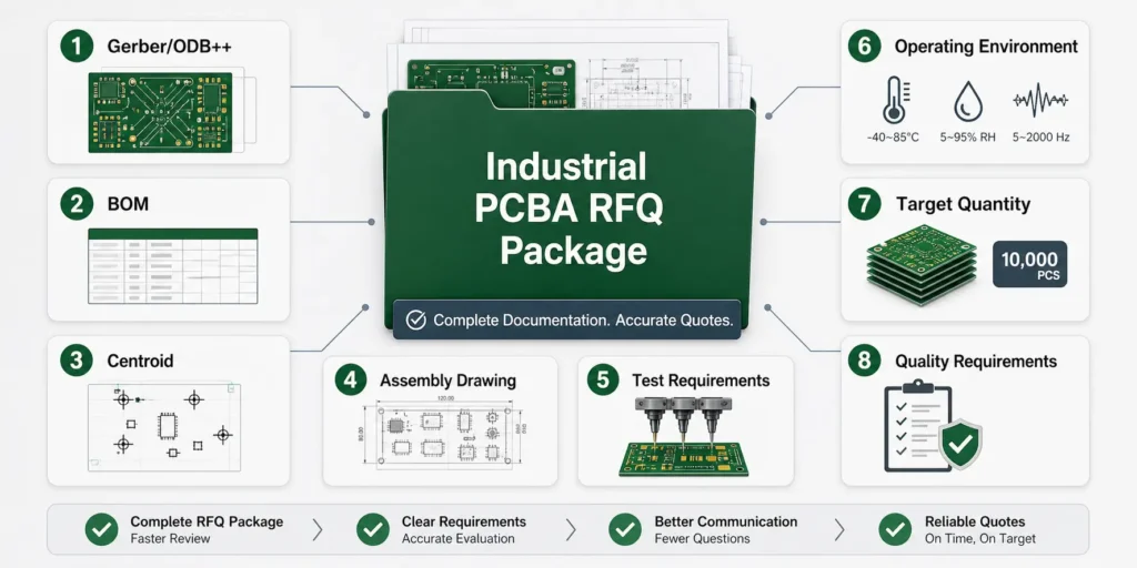
For industrial control PCB assembly, buyers should define the engineering files, BOM requirements, assembly method, operating environment, expected lifetime, quality expectations, testing strategy, programming needs, traceability requirements, target quantity, and schedule. A supplier should not have to guess whether the board is a low-risk indoor controller, a high-current motor control PCBA, an outdoor sensor module, or a long-life automation product.
Incomplete files and vague requirements create avoidable problems: wrong assumptions, inaccurate pricing, slow quotations, late engineering questions, and production schedule risk.
The Minimum Information a PCBA Supplier Needs
A reliable industrial PCBA supplier will normally need the following information before preparing an accurate quotation and manufacturing review:
| File / information | Main purpose |
|---|---|
| Gerber or ODB++ files | PCB layout, layer structure, copper, solder mask, paste layer, drilling, and fabrication details |
| Bill of Materials (BOM) | Full component list with manufacturer, MPN, package, tolerance, voltage/current rating, temperature rating, and approved alternates if available |
| Centroid / pick-and-place file | X/Y coordinates, rotation, side, and reference designators for SMT placement |
| Assembly drawing | Component orientation, polarity, connector direction, hardware notes, reference designators, and special assembly instructions |
| Schematic, if needed | Supports functional test development, troubleshooting, and engineering review |
| Test requirements | ICT, flying probe, functional test, programming, calibration, burn-in, or customer-specific test scope |
| Operating environment | Temperature, humidity, dust, vibration, chemical exposure, outdoor/coastal risk, cabinet conditions, and power environment |
| Expected lifetime | Supports BOM lifecycle planning, approved alternates, traceability, and long-term production planning |
| Target quantity and schedule | Prototype quantity, pilot run, annual forecast, first-order quantity, and target lead time |
| Quality requirements | IPC class, inspection standard, traceability level, reports, serialization, and customer-specific acceptance criteria |
The operating environment drives many manufacturing decisions: component derating, solder joint risk, cleaning, conformal coating, test coverage, and packaging. Expected lifetime is just as important. Industrial products often need EOL monitoring, PCN review, AVL control, approved alternates, and repeat production support long after the first order ships.
Why Industrial PCBA Should Not Be Quoted Like a Simple Consumer Board
Consumer electronics PCBA quotes often revolve around component cost, assembly price, and speed. Industrial control PCBA needs a broader review because the cost of failure is usually much higher.
Important differences include:
- Reliability over lowest price: A failed industrial control board may cause equipment downtime, service travel, emergency replacement, customer complaints, and lost production time.
- Higher testing coverage: Many industrial boards need more than AOI and visual inspection. Depending on the risk level, the project may require X-ray, ICT, flying probe, functional testing, firmware programming, burn-in, power load testing, or environmental review.
- Connector and terminal robustness: Screw terminals, pluggable connectors, relays, transformers, high-current parts, and heavy wire interfaces all need mechanical and soldering review.
- Long-term supply assurance: Industrial products often require repeat builds over many years. Component lifecycle, approved alternates, and AVL control should be part of the sourcing discussion.
- Cleanliness and protection: Flux residue, ionic contamination, humidity, and condensation can cause delayed failures. Cleaning and conformal coating decisions belong in the pre-production stage.
- Full traceability: Lot codes, date codes, inspection records, process history, rework records, and test data may be needed for audits and failure analysis.
Treating an industrial control PCBA like a simple commercial board may reduce the initial quote slightly, but that saving can disappear through rework, schedule delay, hidden test cost, or field reliability problems.
What Is Industrial Control PCB Assembly?
Industrial control PCB assembly is the manufacturing process for PCBAs used in automation, machine control, power management, sensing, communication, actuation, monitoring, and industrial equipment systems.
Depending on project scope, it can include PCB fabrication, component sourcing, SMT assembly, through-hole assembly, mixed assembly, soldering, inspection, firmware programming, functional testing, traceability records, cleaning, conformal coating, packaging, and higher-level box build integration.
Definition of Industrial Control PCB Assembly
Industrial control PCB assembly refers to board-level manufacturing for PCBA used in industrial products. These assemblies are usually expected to support continuous operation, repeatable production quality, controlled sourcing, and higher reliability than many short-lifecycle consumer products.
Typical industrial control PCBA projects may include:
- PCB fabrication
- SMT assembly
- Through-hole assembly
- Hybrid SMT and THT process
- Component sourcing or kitted assembly
- First article inspection
- AOI, SPI, X-ray, or manual inspection
- ICT, flying probe, or functional testing
- Firmware programming
- Calibration or configuration
- Cleaning or conformal coating
- Serial number control and traceability
- Final inspection and export packaging
The right process depends on product risk, production volume, buyer requirements, and the application environment.
Common Industrial Control Products
Industrial control PCB assemblies appear in many equipment and module types, including:
- PLC modules and I/O expansion boards
- HMI control boards
- Motor controller PCB assemblies
- VFD, servo drive, and stepper motor driver boards
- Industrial sensor interface boards
- Power control boards
- AC/DC and DC/DC control modules
- Relay control boards
- Safety interlock boards
- Industrial IoT gateways
- Data acquisition modules
- RS-485, CAN, Ethernet, Profibus, EtherCAT, and other communication boards
- Battery management and charging control boards
- LED industrial lighting control PCBAs
- Equipment monitoring and diagnostic boards
These products often combine low-voltage logic, firmware, communication, power conversion, protection circuits, relays, connectors, terminal blocks, optocouplers, sensors, and mechanical interfaces. That mix makes manufacturability and testing more important than it would be on a simple single-function board.
Industrial PCB Assembly vs Standard Consumer PCB Assembly
Industrial PCB assembly and standard consumer PCB assembly may use many of the same process names: SMT, reflow soldering, through-hole assembly, wave soldering, AOI, X-ray, and functional testing. The difference is the level of risk and control behind those processes.
| Aspect | Industrial control PCBA | Standard consumer PCBA |
|---|---|---|
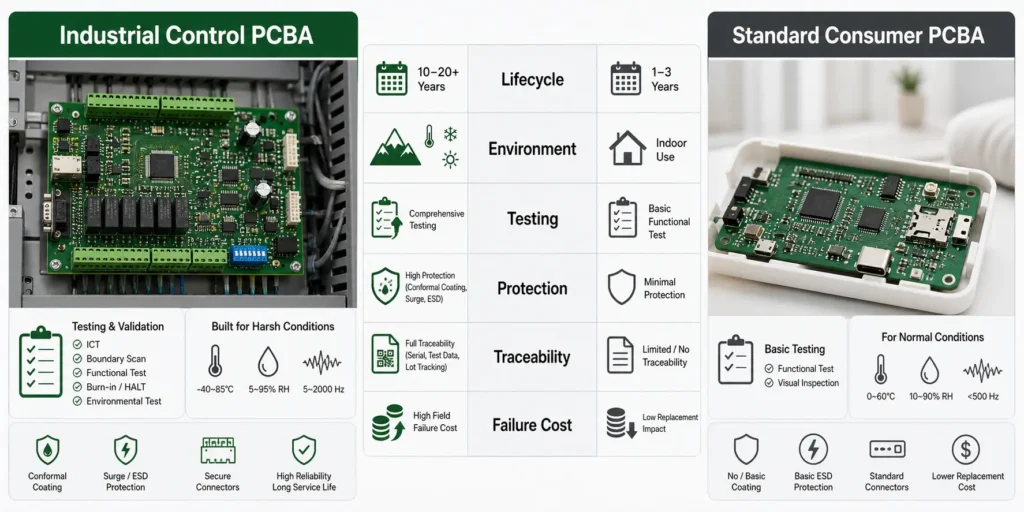
| Lifecycle | Often 5 to 15+ years, depending on product | Often shorter lifecycle and faster model changes |
| Volume | Often prototype, low-volume, medium-volume, or repeat batch production | Often high-volume and cost-optimized |
| Environment | Heat, humidity, dust, vibration, EMI, power noise, cabinet conditions, or outdoor risk | Usually more controlled indoor environment |
| Test coverage | May require AOI, X-ray, ICT, flying probe, FCT, burn-in, or customer-specific validation | Often AOI plus basic functional test |
| Standards | Often IPC Class 2 or customer-defined higher reliability requirements; some projects may require sector-specific standards | Often IPC Class 1 or Class 2 depending on product |
| Protection | Cleaning and conformal coating may be needed | Often not required |
| Traceability | Lot, date code, process record, inspection record, and test result traceability may matter | Traceability may be lighter depending on product |
| Rework impact | Field repair is expensive and downtime-sensitive | Rework or replacement may be less costly |
Industrial control PCBA suppliers should therefore be evaluated on more than price. Engineering review, process control, component sourcing, test support, traceability, and communication all affect the true project outcome.
Why Industrial Control PCBA Requires Higher Reliability
Industrial control boards operate inside real systems, not ideal lab conditions. A board may pass a short factory power-on test and still fail later if the environment, component selection, soldering process, test access, cleanliness, coating, or connector stress was not reviewed with enough care.
Reliability comes from the whole manufacturing plan: design, materials, assembly process, inspection, testing, documentation, and long-term supply control.
Harsh Operating Environments
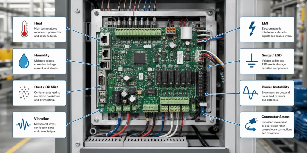
Industrial control PCB assemblies may face:
- Temperature extremes or thermal cycling inside cabinets
- Heat from power devices, transformers, relays, regulators, or nearby equipment
- Humidity, condensation, or coastal air
- Dust, oil mist, cutting fluid residue, or airborne contamination
- Vibration from motors, pumps, compressors, conveyors, and transport
- Electrical noise from inverters, contactors, solenoids, relays, and high-current switching
- Surge, ESD, brownouts, unstable power, or grounding issues
- Mechanical stress from terminal blocks, connectors, cables, and enclosure fit
For some applications, this pushes the design toward wider temperature ratings, stronger derating, better thermal paths, enhanced input protection, additional spacing, conformal coating, or more complete functional testing.
Long Product Lifecycle and Replacement Difficulty
Industrial machinery and automation systems often remain in service for years. During that time:
- The PCBA may need repeat production after the first order
- Components may become obsolete
- Alternate parts may need engineering approval
- Firmware versions and hardware revisions must be controlled
- Test fixtures must remain usable for future builds
- Field replacement can be expensive and time-sensitive
- Traceability records may be needed for root-cause analysis
This long lifecycle changes the sourcing strategy. Turnkey suppliers may need to monitor availability, communicate lead time changes, request alternate approval, and support stable repeat production. Buyers should not wait for a shortage before discussing lifecycle risk.
Failure Modes That Matter in Industrial Electronics
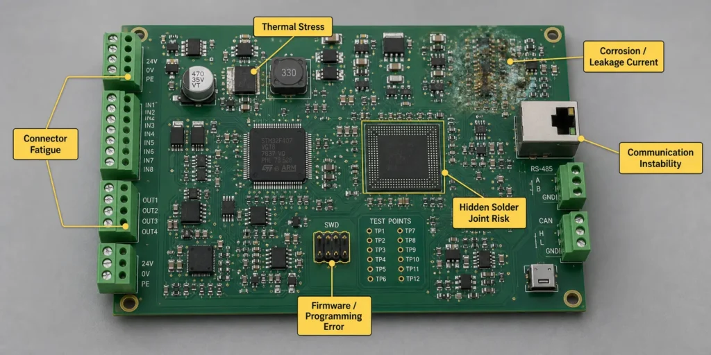
Industrial PCBA failures often come from combined stresses rather than a single obvious defect. Common risk areas include:
- Intermittent failure: Opens, shorts, resets, or signal faults that appear only under temperature, vibration, or load.
- Cold solder joints and solder fatigue: Mechanical and thermal stress can weaken joints around large parts, connectors, BGAs, QFNs, and high-current areas.
- Connector fatigue: Repeated mating, cable pull, vibration, and enclosure movement can crack solder joints or deform contacts.
- Corrosion: Humidity, ionic residue, sulfur, chlorine, salt mist, and contamination can damage exposed metal surfaces.
- Leakage current: Flux residue, dust, moisture, and contamination can create parasitic paths, especially in high-impedance circuits.
- Communication instability: CAN, RS-485, Ethernet, UART, or wireless modules can fail because of grounding, noise, marginal components, poor layout, or firmware mismatch.
- Thermal stress: MOSFETs, regulators, transformers, relays, high-current terminals, and power traces can create hot spots.
- Power input failure: Inrush current, surge, reverse polarity, brownout, or unstable input voltage can damage protection circuits.
- Firmware or programming error: Wrong firmware version, incomplete programming, or missing checksum verification can cause functional failures even when assembly quality is good.
These failure modes shape the entire manufacturing plan, from DFM and DFT to inspection, test coverage, cleaning, coating, and sourcing control.
Key Design and Manufacturing Factors for Industrial PCB Assembly
Industrial PCB assembly quality starts before a panel reaches the SMT line. Stackup, copper weight, thermal path, component package, connector selection, high-voltage spacing, assembly process, panelization, test access, and coating requirements all influence yield and reliability.
PCB Stackup, Copper Weight, and Thermal Design
Industrial control boards often combine signal circuits, communication interfaces, power regulation, relays, and high-current paths. The PCB must support both electrical performance and stable manufacturing.
Important review points include:
- Layer count and stackup structure
- Copper weight and current capacity
- Thick copper or heavy copper requirements
- Thermal relief and solderability of large copper areas
- Heat spreading for MOSFETs, regulators, drivers, transformers, and power devices
- Thermal vias under power components when appropriate
- Isolation between high-voltage and low-voltage areas
- Grounding and return path strategy
- Controlled impedance for Ethernet, CAN, RF, or high-speed signals when required
- Surface finish selection based on assembly, shelf life, and reliability needs
- Via tenting, plugging, or filling requirements where solder wicking or contamination risk exists
High-current and power boards deserve early thermal review. A PCBA that behaves well on an open bench may run very differently inside a sealed enclosure, hot cabinet, or high-load duty cycle.
SMT, THT, and Mixed Assembly
Industrial control PCB assembly frequently combines multiple attachment methods because different components carry different electrical and mechanical demands.
SMT is commonly used for:
- Microcontrollers
- Memory
- ICs and logic devices
- Small passives
- Communication chips
- Sensors
- Optocouplers
- Power management ICs
- Fine-pitch connectors
- QFN, LGA, or BGA packages
Through-hole assembly is commonly used for:
- Screw terminals
- Pluggable connectors
- Relays
- Transformers
- Large electrolytic capacitors
- Fuses and holders
- Power inductors
- Switches
- High-current parts
- Mechanically stressed components
A mixed assembly process may involve top-side SMT, reflow, bottom-side SMT when needed, second reflow, through-hole insertion, wave or selective soldering, inspection, programming, and functional testing. The final flow depends on board design, part placement, thermal mass, soldering access, and quality requirements.
Connectors, Terminal Blocks, and Mechanical Stress
Connectors are often the weak point in industrial PCBA because they link the board to power input, sensors, motors, relays, actuators, communication cables, HMIs, and external equipment.
Buyers and designers should review:
- Cable pull direction
- Connector height and enclosure clearance
- Solder joint stress from repeated insertion
- Vibration exposure
- High-current terminal heating
- Pin plating compatibility
- Locking mechanism or retention force
- Mounting holes, standoffs, clips, or mechanical reinforcement
- Keep-out areas for coating and cleaning
- Labeling and wiring clarity for final assembly
For connectors exposed to heavy cable stress, solder joints should not carry the mechanical load alone. The mechanical design should move stress away from soldered pins wherever possible.
Creepage, Clearance, and High-Voltage Areas
Industrial control boards may include high-voltage input, relay outputs, motor control, isolated communication, or power conversion. Creepage and clearance should be defined according to the applicable product standard, voltage, pollution degree, material CTI, coating strategy, and customer requirements.
Buyers should provide:
- Maximum operating voltage
- Transient or surge requirement if known
- Current rating
- Isolation requirement
- Safety or customer standard requirements
- Required slots, grooves, or cutouts
- Coating requirement and coating keep-out areas
- Insulation or high-voltage test requirements if applicable
The PCBA manufacturer may not be responsible for final safety certification, but manufacturing review can still catch practical risks: solder mask concerns, missing spacing information, coating conflicts, insufficient keep-out areas, assembly access problems, or test limitations.
DFM Checklist for Industrial Control PCB Assembly
DFM, or design for manufacturability, reduces avoidable defects before production. For industrial control PCBA, the review should focus on practical assembly risks: SMT yield, through-hole soldering, connector strength, inspection access, cleaning and coating compatibility, panelization, and testability.
The points below are practical starting points. Final rules should be confirmed with the PCB fabricator, assembly supplier, product standard, and component datasheets.
SMT Manufacturability Checks
For SMT assembly, review:
- Fiducial marks: Use global fiducials for board alignment and local fiducials for fine-pitch or BGA areas when needed.
- Component spacing: Leave enough space for placement nozzles, solder joint formation, AOI inspection, cleaning, and rework.
- Polarity marks: Diodes, LEDs, tantalum capacitors, electrolytic capacitors, IC pin 1, and connectors need clear orientation marks.
- BGA/QFN/LGA design: Review pad style, via-in-pad requirements, solder mask definition, X-ray inspection needs, and stencil aperture design.
- Fine-pitch and small passives: 0201 or 01005 components require stronger process control, correct stencil design, and supplier capability confirmation.
- Stencil apertures: Fine-pitch devices may require special aperture reductions, step stencils, or nano coating depending on design.
- Tall components: Check placement sequence, reflow shadowing, nozzle access, and enclosure clearance.
- Panelization: Review V-score, mouse bites, breakaway tabs, tooling holes, board edge clearance, and depanelization stress.
- Bottom-side components: Confirm whether the design requires adhesive, second reflow support, or selective soldering clearance.
The purpose is to reduce tombstoning, bridging, insufficient solder, skew, voiding, head-in-pillow risk, solder balls, warpage, manual rework, and inspection blind spots.
Through-Hole and Connector Assembly Checks
For through-hole and connector-heavy designs, review:
- Hole diameter vs lead diameter
- Annular ring size
- Component body clearance
- Thermal relief around high-copper pins
- Connector orientation
- Wave soldering or selective soldering compatibility
- Solder bridging risk
- Solder thieves or pad design for dense connectors where appropriate
- Bottom-side clearance for wave solder fixtures or selective solder nozzles
- Mechanical anchors for heavy connectors, transformers, or large capacitors
- Cleaning and coating access around connectors and terminal blocks
Through-hole parts may provide stronger mechanical bonding, but they also add labor, process steps, thermal mass, and inspection requirements. The RFQ should identify these parts clearly so the supplier can plan the assembly flow and cost correctly.
DFT and Test Point Planning
DFT, or design for testability, should be handled before PCB release. Industrial control boards often require ICT, flying probe, firmware programming, calibration, functional test, or system-level verification.
Buyers and designers should consider:
- Test point access from one or both sides
- Ground and power test points
- Programming ports such as JTAG, SWD, UART, SPI, CAN, or customer-specific headers
- Fixture probe access and keep-out zones
- Test pad size and spacing based on the chosen fixture or flying probe method
- Relay, I/O, sensor, and communication test access
- Barcode, serial number, or QR code location
- Firmware version verification
- Calibration method and calibration data storage
- Pass/fail criteria and data logging
Missing test access can increase fixture cost, reduce flying probe coverage, and force manual workarounds during functional testing. A small layout adjustment before production can save a great deal of time during NPI and pilot runs.
Testing Strategy for Industrial Control PCBA
Industrial control PCBA testing should be risk-based. Not every project needs every test, but every project needs a defined strategy. The right plan depends on board function, production volume, defect risk, field failure cost, customer requirements, and project stage.
Inspection Methods: SPI, AOI, X-Ray, and Visual Inspection
Common inspection methods include:
| Method | What it detects well | Limitations |
|---|---|---|
| SPI | Solder paste volume, height, area, offset, bridging risk before reflow | Checks paste only, not final joint reliability |
| AOI | Missing parts, wrong parts, polarity, tombstoning, skew, bridging, visible solder defects | Cannot fully inspect hidden joints under BGA, QFN, shields, or dense packages |
| X-ray | Hidden solder joints, BGA solder balls, QFN voiding, shorts under components, some via and solder fill issues | Slower and usually applied to selected risk areas, not always every solder joint |
| Visual inspection | Connectors, labels, through-hole joints, mechanical parts, contamination, coating, scratches, final appearance | Operator-dependent and limited for fine-pitch or hidden defects |
For industrial boards, AOI with selected X-ray inspection for BGA, QFN, or other hidden-joint areas is a common approach. SPI is especially useful for process control because poor paste printing creates defects before placement and reflow.
Electrical Testing: ICT vs Flying Probe
ICT and flying probe testing help detect electrical faults, but they fit different production stages and volumes.
| Factor | ICT | Flying probe |
|---|---|---|
| Fixture | Requires dedicated bed-of-nails fixture | Usually no dedicated fixture |
| Setup cost | Higher upfront fixture cost | Lower setup cost |
| Test speed | Fast after fixture is built | Slower per board |
| Flexibility | Less flexible after design change | More flexible for revisions |
| Best fit | Stable medium-to-high volume designs | Prototype, NPI, low-volume, high-mix, or changing designs |
| Requirement | Good test point access and stable layout | Still needs access, but can be more flexible |
For industrial control projects, flying probe often fits prototype and pilot builds. Once the design is stable and volume increases, ICT may reduce per-board test time if the fixture cost is justified. Some industrial projects stay with flying probe because volumes are irregular or board variants change often.
Functional Testing for Industrial Control Boards
Functional testing is often the most important test for industrial control PCBA. It verifies whether the board performs its intended function, not just whether components were placed correctly.
Depending on the design, FCT may include:
- Power rail verification
- Input voltage range test
- Output voltage and load check
- Ripple or startup sequence measurement
- Digital input and output test
- Analog input and output test
- 4-20 mA current loop test when applicable
- Relay actuation and contact check
- Communication test such as RS-485, CAN, Ethernet, UART, USB, or wireless module verification
- Firmware programming and checksum verification
- Sensor simulation
- Motor driver or load simulation
- LED, display, buzzer, or button test
- Calibration or configuration
- Protection circuit check
To quote and build FCT correctly, the supplier needs the test procedure, firmware, programming instructions, fixture requirements, load conditions, test cables, acceptance limits, and data recording requirements.
Reliability Testing: Burn-In and Environmental Checks
Industrial control PCBA may need additional reliability testing when the application risk is high or the buyer requires validation evidence.
Possible tests include:
- Burn-in or power aging to screen early failures
- Temperature cycling for solder joint and material stress
- Temperature and humidity testing for moisture-related risk
- Vibration or transportation simulation
- Salt spray or corrosion-related testing for coastal or corrosive environments
- Power load testing for high-current assemblies
- Long-duration operating test
- Communication stability test
- Battery charge/discharge or protection testing when relevant
These tests add cost, schedule time, sample usage, and engineering effort, so they should match the real environment. A climate-controlled indoor control board may not need salt spray testing; a coastal outdoor module may need a more serious environmental review.
Cleaning, Conformal Coating, and Environmental Protection
Industrial electronics may be exposed to humidity, dust, oil mist, condensation, flux residue, corrosive gases, or long service-life requirements. Cleaning and conformal coating can help, but only when they are planned correctly.
When Industrial PCBA Needs Cleaning
Even with no-clean flux, residues may remain under low-standoff components, around fine-pitch devices, or in high-impedance areas. In low-risk products, this may be acceptable under a controlled process. In higher-risk industrial products, cleaning or cleanliness verification may be needed.
Cleaning should be discussed when:
- The board operates in humid or condensing environments
- The design includes high-impedance analog circuits
- The board has fine-pitch ICs or low-standoff packages
- The product will be conformal coated
- Leakage current matters
- The product needs long service life
- The customer defines cleanliness requirements
- Flux residue may affect corrosion, coating adhesion, or electrical stability
Cleanliness criteria should come from customer requirements, product risk, applicable standards, and validated process evidence. A single generic cleanliness number is rarely enough without considering the actual application.
When Conformal Coating Is Recommended
Conformal coating may be useful for industrial PCB assemblies exposed to:
- Humidity
- Condensation
- Dust
- Chemical or corrosive air
- Coastal environments
- Outdoor installation
- Temperature cycling
- Long-life service requirements
- Harsh control cabinet conditions
Common coating material families include:
| Coating type | Advantages | Limitations |
|---|---|---|
| Acrylic | Easy to apply and rework, good general moisture protection | Lower chemical resistance than some alternatives |
| Polyurethane | Good chemical and abrasion resistance | Harder to rework and may require stricter process control |
| Silicone | Good flexibility and wide temperature tolerance | Lower abrasion resistance and compatibility must be checked |
| Parylene | Very uniform coating and strong barrier performance | Higher cost, specialized process, difficult rework |
The best coating depends on the environment, component compatibility, rework needs, cost, reliability target, and customer requirements. Coating cannot compensate for poor design or weak process control.
Coating Keep-Out Areas Buyers Must Define
Before coating, buyers should define keep-out areas in the assembly drawing or a dedicated coating drawing.
Typical keep-out areas include:
- Connector contact points
- Terminal block mating surfaces
- Test points
- Programming headers
- Switches and buttons
- Potentiometers
- Optical, pressure, flow, or environmental sensor openings
- Battery contacts and fuse holders
- Heat sinks or thermal contact areas
- Grounding pads or EMI gasket contact areas
- Labels, QR codes, or serial numbers that must remain readable
Without clear keep-out information, the supplier may need extra engineering communication, masking labor, rework, or process trials. For industrial products, coating belongs in the manufacturing plan from the start.
BOM and Supply Chain Control for Industrial PCBA
Industrial control products often remain in production or service for many years. BOM management is therefore a reliability and delivery issue, not just a purchasing task.
Why Long-Life BOM Management Matters
Industrial PCBA buyers should pay attention to:
- Manufacturer part number
- Approved manufacturer
- Lifecycle status
- Lead time
- Package and footprint compatibility
- Electrical rating
- Temperature rating
- Tolerance
- Firmware or programming compatibility
- Mechanical fit
- Country of origin or customer restrictions when relevant
- Minimum order quantity and excess inventory risk
If a BOM lists only generic descriptions such as “10k resistor” or “4-pin connector,” the supplier cannot reliably control repeatability. A production-ready BOM should include approved MPNs, manufacturer names, package details, ratings, and substitute rules.
EOL, PCN, and Long-Term Support
For long-life industrial products, component lifecycle must be watched. Common risks include:
- EOL components with no drop-in replacement
- PCN changes affecting package, marking, material, or electrical behavior
- Long lead-time parts delaying production
- Counterfeit risk when parts are sourced urgently
- Last-time-buy opportunities missed because no one tracked lifecycle status
- Redesign required because alternates were not approved early
For critical components such as MCUs, FPGAs, communication chips, power devices, sensors, relays, connectors, and custom magnetics, buyers should identify risk early and define how alternates will be approved.
Approved Alternates and AVL Control
Approved alternates reduce shortage risk without giving up engineering control. An alternate should be reviewed for:
- Electrical parameters
- Pinout
- Package and footprint
- Temperature rating
- Voltage and current rating
- Tolerance
- Timing, communication, or firmware compatibility
- Mechanical fit
- Thermal behavior
- Compliance or customer-specific restrictions
Simple passives are often easier to approve. ICs, relays, connectors, sensors, power semiconductors, and communication modules may require sample testing or formal engineering approval before production use.
Turnkey vs Consigned vs Partial Turnkey Sourcing
Industrial PCBA can be sourced through turnkey, consigned, or partial turnkey models.
| Model | How it works | Best fit |
|---|---|---|
| Turnkey PCBA | Supplier handles PCB fabrication, component sourcing, and assembly | Buyers who want a single point of contact and supplier-managed sourcing |
| Consigned / kitted PCBA | Buyer supplies all or key components to the assembler | Buyers with controlled inventory, approved suppliers, or sensitive components |
| Partial turnkey / combo | Buyer supplies critical parts; supplier sources standard parts | Industrial projects where critical ICs are controlled but passives/connectors can be sourced by the supplier |
PCBAgroup’s public PCB assembly service page describes consigned/kitted, turn-key, and partial turn-key/combo options. For industrial projects, partial turnkey is often practical because the buyer can control long-lead or sensitive parts while the supplier manages standard sourcing and assembly.
Cost and Lead Time Drivers in Industrial PCB Assembly
Industrial PCBA cost should be evaluated as total project cost, not only unit assembly price. A quote that excludes test fixtures, functional testing, cleaning, coating, traceability, programming, sourcing review, or engineering support may look cheaper than it really is.
Main Cost Drivers
Common industrial PCB assembly cost drivers include:
- PCB layer count and stackup complexity
- Heavy copper or thick copper requirements
- Controlled impedance or high-frequency requirements
- Blind/buried vias, via-in-pad, filled vias, or HDI features
- Fine-pitch ICs, BGA, QFN, 0201, or 01005 components
- Component sourcing cost and long lead-time parts
- Mixed SMT and through-hole assembly
- Large connectors, relays, transformers, terminal blocks, and power components
- Selective soldering, wave soldering, or manual soldering labor
- ICT or FCT fixture development
- Firmware programming and calibration
- Cleaning and cleanliness verification
- Conformal coating, masking, and curing
- Traceability, serialization, and reporting
- Low-volume setup cost
- Special packaging or export requirements
Quotes should be compared by scope. A lower assembly number that excludes functional testing, coating, or fixture work may not be the lower project cost.
Common Causes of Lead Time Delay
Industrial PCBA delays often come from incomplete information or late engineering decisions.
Common causes include:
- Missing BOM information
- Long lead-time or obsolete components discovered after RFQ
- No approved alternates
- Centroid file does not match BOM
- Assembly drawing lacks polarity or connector notes
- Test procedure not ready
- Firmware not released before production
- Fixture requirements discovered too late
- Engineering changes after order placement
- Coating and cleaning requirements added late
- Mechanical fit issues with enclosure or connectors
- Customer approval delays for substitute parts
A complete RFQ package reduces back-and-forth communication and helps prevent delays before materials are ordered.
How to Reduce Cost Without Reducing Reliability
Cost reduction in industrial control PCB assembly should remove avoidable complexity and rework, not necessary reliability controls.
Practical methods include:
- Complete DFM review before production
- Use standard component packages where possible
- Avoid unnecessarily small components if board space allows
- Reduce the number of unique connectors
- Pre-approve alternate components
- Use panelization to improve assembly efficiency
- Choose flying probe for low-volume or early-stage projects when ICT fixture cost is not justified
- Transition to ICT when volume and design stability justify fixture investment
- Combine functional test steps efficiently
- Define coating and masking requirements early
- Release stable firmware before production
- Plan prototype, pilot run, and mass production differently
- Batch orders when possible to reduce setup cost per unit
Every cost-down decision needs to be checked against product risk. A cheaper part, thinner board, reduced test plan, or simplified coating process can create higher cost later if it increases field failure risk.
Industrial Control PCBA RFQ Checklist
A complete RFQ package helps the supplier quote accurately, review risks earlier, and compare manufacturing scope more fairly.
Engineering Files
Include:
| File | Required? | Notes |
|---|---|---|
| Gerber or ODB++ | Yes | Latest revision with copper, solder mask, paste, drill, and board outline |
| BOM | Yes | MPN, manufacturer, package, rating, tolerance, approved alternates, DNI/DNP notes |
| Centroid / pick-and-place file | Yes | X/Y, rotation, side, reference designator |
| Assembly drawing | Yes | Orientation, polarity, mounting holes, connector direction, special notes |
| Schematic | Helpful for test | Useful for FCT, troubleshooting, programming, and engineering review |
| PCB stackup | If controlled | Important for impedance, thickness, copper, and material requirements |
| Mechanical / STEP files | Recommended when enclosure fit matters | Helps check connectors, height, mounting, and keep-out conflicts |
| Revision history | Recommended | Helps avoid building the wrong revision |
Manufacturing and Quality Requirements
Define:
- IPC class or customer workmanship requirement
- SMT, THT, or mixed assembly scope
- Solder alloy and RoHS requirement
- Flux type if required
- PCB surface finish
- Cleaning requirement
- Cleanliness verification requirement, if any
- Conformal coating type, thickness, coverage, and keep-out zones
- Traceability level
- First article inspection requirement
- Inspection reports or test reports
- Packaging and labeling requirements
- Serialization or barcode requirements
Testing and Programming Requirements
Provide:
- Required inspection method: AOI, SPI, X-ray, visual inspection
- ICT or flying probe requirement
- Functional test procedure
- Test point coordinates if available
- Firmware files and version control instructions
- Programming tools or adapters
- Test cables and fixture requirements
- Load conditions
- Calibration requirements
- Pass/fail criteria
- Data logging or report format
Application and Commercial Information
Share:
| Information | Why it matters |
|---|---|
| Operating environment | Affects component rating, cleaning, coating, testing, and packaging |
| Product application | Helps supplier understand risk and function |
| Expected lifetime | Supports BOM lifecycle and traceability planning |
| Prototype quantity | Helps choose NPI process and test method |
| Pilot quantity | Helps validate production readiness |
| Annual volume | Helps sourcing, fixture, and inventory decisions |
| Target lead time | Helps capacity and material planning |
| Critical components | Identifies parts needing approval or special sourcing |
| Packaging requirement | Affects ESD, moisture, shipping, and labeling process |
Providing this information upfront can shorten the RFQ cycle and reduce late surprises.
How PCBAgroup Supports Industrial Control PCB Assembly Projects
PCBAgroup is based in Shenzhen, China and provides PCB fabrication and PCB assembly services for electronic products. Public website content describes PCBAgroup as having 15+ years of experience, support from NPI to high-volume production, and a stable sourcing network for component selection, procurement, final assembly, and testing.
For PCB assembly, PCBAgroup’s service page describes support for SMT, through-hole, and hybrid assembly; consigned/kitted, turn-key, and partial turn-key/combo sourcing models; leaded and lead-free RoHS-compliant assembly; laser-cut stainless steel stencils; and small-batch minimum order support. The site also lists industrial control, smart home, medical, automotive, IoT, telecom, LED, electronics, and other application areas.
For quality control, PCBAgroup’s public quality page describes MES traceability, process review, IQC, SPI solder paste inspection, online AOI, first sample testing, offline AOI, X-ray welding inspection, and QC manual inspection. The about page also states that PCBAgroup operates 8 high-speed SMT production lines with equipment including Panasonic NPMD3, TT2, and CM602, 10-zone reflow ovens, automatic solder paste printers, wave soldering equipment, SPI, X-ray, offline/online AOI, and first-article inspection systems.
Engineering Review Before Production
For industrial control projects, early engineering review is valuable because many problems are cheaper to solve before materials are purchased and the SMT schedule is fixed.
Before prototype, pilot run, or mass production, buyers can ask PCBAgroup to review:
- Gerber or ODB++ completeness
- BOM completeness
- Component sourcing risks
- Approved alternates
- Centroid and BOM consistency
- Assembly drawing clarity
- SMT and through-hole manufacturability
- Connector and terminal block risks
- Test point and fixture access
- Functional test feasibility
- Cleaning and conformal coating needs
- Packaging and labeling requirements
This review can reduce preventable delays and align technical expectations before production starts.
Manufacturing and Inspection Capability Signals
Based on PCBAgroup’s public website content, relevant capability signals for industrial control PCB assembly include:
- PCB fabrication and PCBA services
- SMT assembly
- Through-hole assembly
- Hybrid SMT and THT assembly
- Turnkey, consigned/kitted, and partial turnkey assembly options
- Leaded and lead-free RoHS-compliant assembly
- Laser-cut stainless steel stencils
- Support for small passive components including 01005, 0201, and 0402 as stated on the PCB assembly service page
- Process review
- IQC incoming quality control
- SPI solder paste inspection
- Online and offline AOI
- First sample testing
- X-ray welding inspection
- QC manual inspection
- MES traceability linking process history, materials, operators, machines, parameters, and inspection records
The exact process for each industrial PCBA project should still be selected according to board complexity, product risk, customer requirements, and production volume.
Suitable Project Types
Industrial control PCB assembly support may fit:
- Prototype builds
- NPI builds
- Engineering validation builds
- Pilot production
- Low-volume production
- Medium-volume repeat production
- Turnkey PCBA
- Partial turnkey PCBA
- Consigned/kitted assembly
- Mixed SMT and through-hole assembly
- Industrial modules
- Control boards requiring functional testing
- PCBA-to-box-build integration projects
For overseas buyers in Europe, North America, Australia, and other developed markets, the key is to work with a supplier that can communicate clearly, review files carefully, support engineering questions, and maintain process control from quotation to shipment.
FAQ
What Is Industrial Control PCB Assembly?
Industrial control PCB assembly is the process of manufacturing PCB assemblies used in automation equipment, machine control, sensing, communication, power management, motor control, PLC modules, HMI boards, and other industrial electronics. It normally includes PCB fabrication, component sourcing, SMT assembly, through-hole assembly, inspection, testing, and quality control.
What Files Are Needed for an Industrial PCBA Quote?
For an accurate industrial PCBA quote, provide Gerber or ODB++ files, BOM, centroid file, assembly drawing, target quantity, lead time requirement, operating environment, expected lifetime, test requirements, and any cleaning, conformal coating, programming, traceability, or packaging requirements. If functional testing is needed, include firmware, test procedure, acceptance criteria, test cables, and fixture requirements.
Does Every Industrial PCBA Need Conformal Coating?
No. Not every industrial PCBA needs conformal coating. Coating is more useful when the board may face humidity, condensation, dust, corrosive air, outdoor installation, coastal environments, or long service life requirements. The decision should be based on the real operating environment, board design, customer requirements, maintenance needs, and coating compatibility.
Is Functional Testing Necessary for Industrial Control Boards?
Functional testing is strongly recommended for many industrial control boards, especially when the board includes firmware, communication interfaces, relays, I/O, power outputs, sensors, motor control, or calibration. AOI and visual inspection can confirm many assembly conditions, but they cannot fully verify product function.
Should I Choose Turnkey or Consigned PCBA for Industrial Products?
Choose turnkey PCBA if you want the supplier to manage PCB fabrication, component sourcing, assembly, and production coordination. Choose consigned PCBA if your company controls key components, approved vendors, or allocated parts. Many industrial projects use partial turnkey, where the buyer provides critical parts and the supplier sources standard components.
What Causes Industrial PCBA Lead Time Delays?
Common lead time delays include incomplete BOMs, long lead-time components, missing approved alternates, unclear test requirements, late firmware release, centroid and BOM mismatch, missing polarity notes, connector or enclosure fit issues, and cleaning or coating requirements that were not defined during RFQ review.
How Can Buyers Reduce Industrial PCBA Cost Without Reducing Reliability?
Buyers can reduce cost by improving DFM, standardizing components, approving alternates early, choosing a test plan that matches product risk, improving panelization, reducing unnecessary manual soldering, clarifying coating requirements, and preventing late engineering changes. The goal is to remove avoidable cost, not remove necessary reliability controls.
Conclusion: Build Industrial PCBA Around Reliability, Not Just Price
Industrial control PCB assembly is different from ordinary low-risk assembly. The operating environment is harsher, the lifecycle is longer, the cost of failure is higher, and the supply chain may need support for years.
A successful industrial PCBA project should integrate:
- Application awareness: Design and process decisions should reflect temperature, humidity, vibration, dust, EMI, power quality, and field service risk.
- DFM and DFT: Manufacturability and testability should be built into the board before production release.
- Inspection and test strategy: AOI, SPI, X-ray, ICT, flying probe, FCT, burn-in, or environmental tests should be selected according to risk and volume.
- Cleaning and coating: Protection processes should be planned where needed, with clear keep-out definitions.
- BOM and sourcing control: Lifecycle status, approved alternates, and sourcing responsibility should be defined early.
- Cost optimization without shortcuts: Standardization, panelization, batch planning, and test strategy can reduce cost without weakening reliability.
Choosing a PCBA partner who understands industrial requirements can reduce hidden cost, schedule delays, rework, and field failures.
If you are preparing an industrial control PCBA project, send PCBAgroup your Gerber or ODB++ files, BOM, centroid file, assembly drawing, test requirements, operating environment, target quantity, and reliability expectations. PCBAgroup can review manufacturability, sourcing, testing, cleaning, coating, and production risks before prototype, pilot run, or mass production.
