Table of Contents
SMT vs SMD: Complete Guide for Electronics Manufacturing & PCB Assembly
Introduction
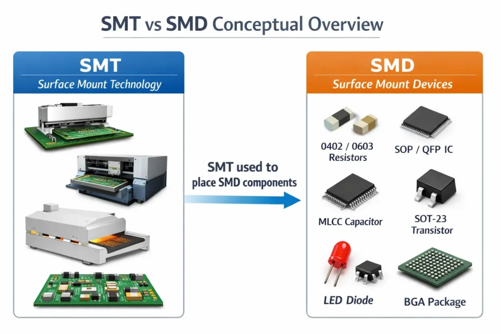
In modern electronics manufacturing, SMT (Surface Mount Technology) and SMD (Surface Mount Device) are terms that often appear together. While closely related, they are fundamentally different: SMT is the assembly process, and SMD refers to the components mounted using that process.
Understanding this distinction is vital for engineers, buyers, and sourcing teams evaluating PCB assembly suppliers or planning production. This guide provides a comprehensive overview, from SMT processes and SMD types to high-density assembly, through-hole comparison, and key considerations for buyers.
What Is SMT?
SMT (Surface Mount Technology) is the most widely used manufacturing process in modern PCB assembly. It involves mounting electronic components directly onto the PCB surface, replacing traditional through-hole methods. SMT enables miniaturization, high-density layouts, automation, and efficient mass production.
Full Meaning of SMT
SMT stands for Surface Mount Technology. Originating in the 1960s, it has become a mature process for modern electronics, forming the backbone of high-speed, automated PCB assembly.
How SMT Works in PCB Assembly
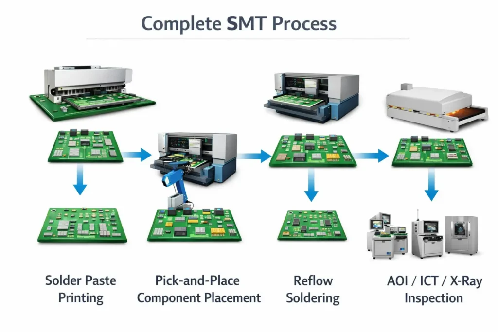
A typical SMT assembly process includes:
Solder Paste Printing: Solder paste is applied to PCB pads via a stencil, providing temporary adhesion for SMDs.
Component Placement: Pick-and-place machines automatically position SMD components on the PCB with high precision.
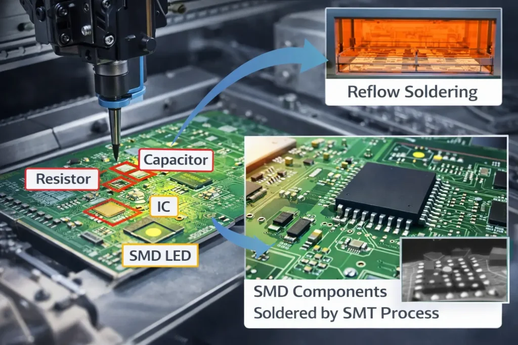
Reflow Soldering: The PCB passes through a reflow oven, melting the solder to create reliable electrical and mechanical connections.
Inspection and Testing: AOI, ICT, and X-Ray systems ensure soldering and assembly quality.
Why SMT Is Widely Used
High-speed automation: Reduces manual labor, increases throughput.
Miniaturization: Supports smaller components and denser layouts.
Reliability: Short leads reduce parasitic inductance and capacitance, improving high-frequency performance.
Cost efficiency: Reduces material use, board area, and rework rates.
What Is SMD?
SMD (Surface Mount Device) refers to the electronic components designed for SMT assembly. These components typically have no leads or very short leads, allowing direct PCB surface mounting.
Full Meaning of SMD
SMD stands for Surface Mount Device. It is sometimes referred to as SMC (Surface Mount Component) in broader contexts. SMDs include resistors, capacitors, ICs, LEDs, and transistors designed for surface mounting.
Common Examples of SMD Components
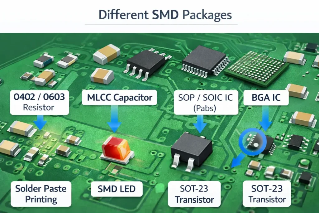
Resistors: 0201, 0402, 0603, 0805 packages.
Capacitors: Multilayer ceramic, tantalum, aluminum electrolytic.
Integrated Circuits (ICs): SOP/SOIC, QFP, BGA, QFN packages.
LEDs: Compact for backlighting or indicators.
Transistors: SOT-23 and other small packages.
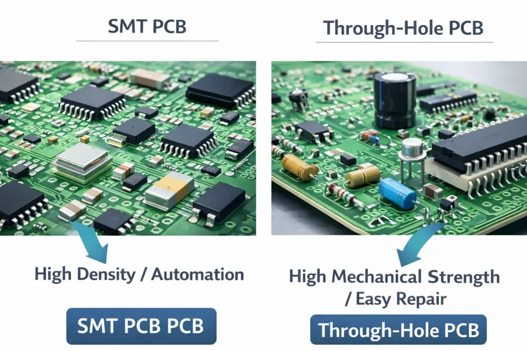
How SMD Components Differ from Through-Hole Components
| Feature | SMD | Through-Hole |
|---|---|---|
| Structure | No or short leads, mounted on surface pads | Long leads inserted through drilled holes |
| Size & Weight | Very small, lightweight | Larger, occupies more PCB space |
| Assembly Density | High | Low |
| High-Frequency Performance | Excellent, low parasitic | Limited by long leads |
| Mechanical Strength | Moderate | High, withstands vibration and shock |
| Production Efficiency | Fully automated | Manual or semi-automated |
| Cost | Efficient for mass production | Higher per unit for large-scale |
SMT vs SMD: The Key Difference
SMT = the process/technology
SMD = the component/device
Many people confuse the terms because both belong to the same assembly ecosystem. In practice, SMDs exist to be mounted using SMT, making them inseparable during manufacturing discussions.
| Term | Full Name | Refers To | Category | Example | Role in PCB Assembly |
|---|---|---|---|---|---|
| SMT | Surface Mount Technology | Assembly method | Process | Reflow soldering, pick-and-place line | Determines “how to assemble” |
| SMD | Surface Mount Device | Component/device | Component | 0402 resistor, QFP IC | Determines “what to assemble” |
How SMT and SMD Work Together in PCB Assembly
SMDs Are Mounted Using SMT
SMT enables accurate, high-speed placement of SMD components. Pick-and-place machines and reflow ovens are designed specifically for SMD characteristics. For example:
BGA components rely on solder balls for SMT alignment.
X-Ray inspection ensures internal solder joint quality.
Reflow soldering’s self-alignment effect corrects minor placement errors.
Example in a Real Manufacturing Workflow
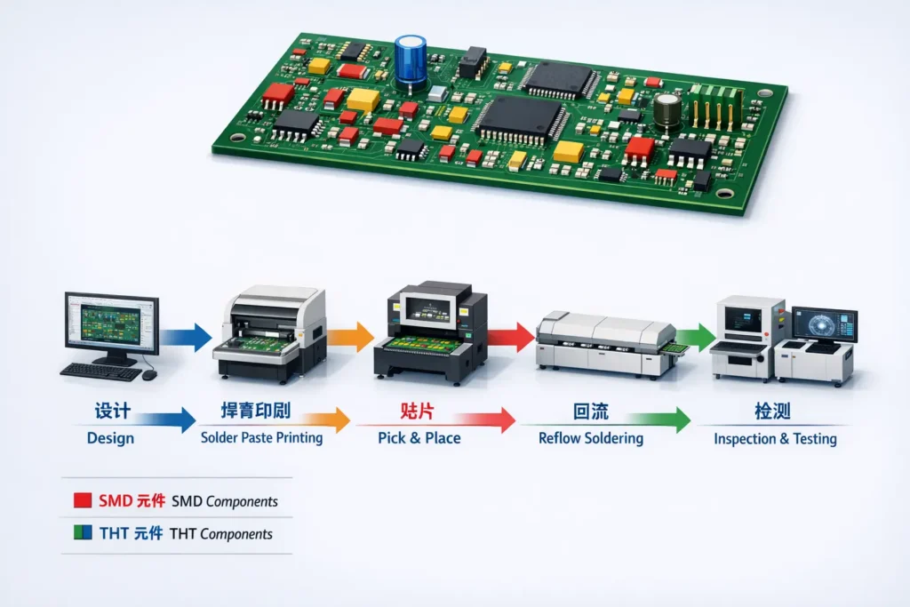
Design & BOM Preparation: PCB design finalized, components listed.
Solder Paste Printing: Paste applied to PCB pads.
SMD Placement: Pick-and-place machine positions components.
Reflow Soldering: Components soldered on PCB.
Inspection & Testing: AOI, ICT, functional tests ensure quality.
Post-Processing: Cleaning, coating, assembly, packaging.
Why This Matters for Buyers and Sourcing Teams
Improves supplier communication: Distinguish “SMT process” vs “SMD components.”
Enhances RFQ clarity: Accurately specify prototypes, full BOM, and assembly needs.
Reduces project risk: Complex SMDs require precise SMT processes for yield.
Controls cost, lead time, and quality: SMD selection and SMT process define manufacturing efficiency.
SMT vs Through-Hole: Is SMT Always Better?
SMT is ideal for high-density, compact, automated production. However, through-hole technology (THT) remains essential when:
High mechanical strength is required (connectors, large transformers).
High power or voltage applications need thicker leads.
Prototype or low-volume boards benefit from easy hand soldering.
Mixed assembly (SMT + THT) is common in modern electronics, combining small SMDs for compact circuits and through-hole for robust components.
When Should Buyers Care About SMT Capability?
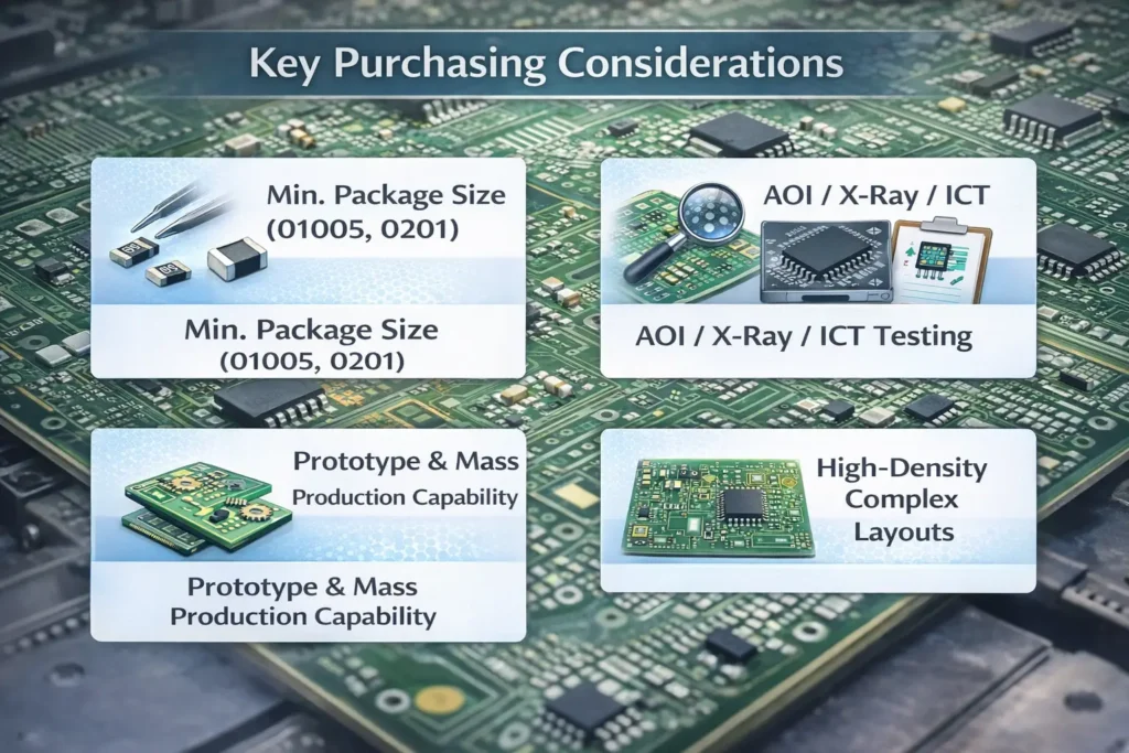
For Prototype and Mass Production Projects
Prototype: Quick-turn services, small batch flexibility.
Mass Production: Evaluate peak capacity, repeatability, production monitoring.
For Product Complexity and Component Density
Miniature components: 01005, 0201, BGA, QFN require high-precision SMT.
High-density layouts: Need precise stencil and pad design.
For Quality Control and Inspection Requirements
SPI, AOI, X-Ray, ICT/FCT for defect prevention.
Environmental control: temperature, humidity, ESD protection.
Compliance: ISO9001, IATF16949, ISO13485 as relevant.
Conclusion
Understanding SMT (process) vs SMD (component) is critical for communicating with manufacturers, evaluating production capabilities, and making informed sourcing decisions.
For buyers, engineers, and project managers, matching design complexity, component selection, and supplier capabilities ensures faster turnaround, consistent quality, and better product performance.
Looking for a reliable PCB assembly partner? Consider suppliers with advanced SMT lines, flexible prototyping, high-density SMD placement, and robust quality control.
FAQ
Q1: What is the difference between SMT and SMD?
A: SMT is the assembly process; SMD is the component used in that process.
Q2: Why are SMT and SMD often confused?
A: Both belong to the same assembly ecosystem; SMT is the process, SMD is the component.
Q3: Is SMT always better than through-hole?
A: SMT is better for high-density automated production, THT is better for mechanical strength and prototyping.
Q4: What should buyers look for in an SMT assembly supplier?
A: Component size capability, complex SMD experience, AOI/X-Ray/ICT/FCT inspection, DFM support, prototype and mass production ability.
Q5: Can all SMDs be assembled using any SMT line?
A: No, some ultra-small or high-density components require specialized equipment and precision processes.
