
Table of Contents
PCBA Reliability Testing Guide: Burn-In, Temperature/Humidity, Vibration, and Salt Spray Testing
A PCBA can pass AOI, X-ray, ICT, and functional testing at the factory and still fail later in the field.
That does not mean those inspection and test methods are weak. It means they answer a different question.
AOI, X-ray, ICT, and FCT help confirm whether the printed circuit board assembly was built correctly and whether it works under the test conditions used before shipment. PCBA reliability testing asks a harder question: will the assembly remain stable after heat, humidity, vibration, shipping stress, salt mist, load cycling, long operating hours, or a harsh installation environment?
For engineers and procurement teams, this distinction matters. A board that works on the bench may still fail in a humid cabinet. A connector that passes functional testing may loosen after transport. A solder joint that looks acceptable after reflow may crack after vibration. A no-clean residue that appears harmless on a dry production line may become a leakage path under humidity and bias.
PCBA reliability testing is not a single test. It is a risk-based validation plan. Depending on the application, it may include burn-in testing, temperature and humidity testing, thermal cycling, vibration testing, simulated transportation testing, salt spray testing, battery charge/discharge validation, high-current load testing, coating validation, cleanliness review, or customer-specific qualification testing.
The goal is not to request every possible test. That usually increases cost, extends lead time, and creates confusion. The goal is to match test depth to the product’s real risk.
This guide explains PCBA reliability testing from a buyer’s point of view. It helps you decide which tests matter, when they are worth the added cost, what each test can and cannot prove, and what to include in your RFQ so your PCBA supplier can quote and plan the project correctly.
Quick Answer: Which PCBA Reliability Tests Should You Request?
The best PCBA reliability test plan depends on five factors:
- Product risk level
- Operating environment
- Expected service life
- Field failure cost
- Customer or industry requirements
For low-risk indoor products, standard PCB assembly quality control plus functional testing may be enough. For industrial, outdoor, battery-powered, high-current, automotive-related, medical-adjacent, or long-life products, extra reliability testing should be considered before pilot run or mass production.
Test Selection by Product Risk Level
Use the table below as a practical starting point. It is not a universal standard. The final plan should be adjusted based on your product design, end-use environment, customer requirements, and acceptance criteria.
| Product risk level | Typical product examples | Reliability testing approach |
|---|---|---|
| Low risk | Simple indoor electronics, short-life accessories, low-current control boards | AOI, visual inspection, basic electrical test, FCT, packaging check; extra reliability tests only if customer requires them |
| Medium risk | Smart home devices, IoT modules, industrial control boards, battery-powered products | FCT plus selected reliability validation such as limited burn-in, temperature/humidity review, power-load testing, or transportation vibration review |
| High risk | Outdoor electronics, power electronics, 24/7 industrial equipment, automotive-related modules, medical-adjacent electronics | Risk-based validation plan covering burn-in, environmental testing, vibration, load testing, documentation, traceability, and customer-specific requirements |
| Critical or regulated risk | Safety-related, transportation, aerospace, medical device, or customer-regulated products | Formal qualification plan led by the customer’s standard, certification path, and product-level compliance requirements |
For B2B PCBA sourcing, the most useful first question is not “Can you do reliability testing?” It is “Which failure modes are we trying to prevent, and which test conditions can realistically reveal them?”
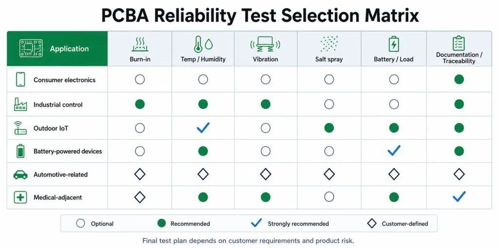
Recommended Test Matrix by Application
| Application | Burn-in | Temperature/humidity | Vibration or transportation | Salt spray | Battery/load testing | Notes |
|---|---|---|---|---|---|---|
| Basic indoor consumer electronics | Optional | Usually not needed unless specified | Packaging review may be enough | Usually not needed | Only if power risk exists | Keep cost controlled; focus on stable assembly and FCT |
| Smart home or connected devices | Optional to recommended | Recommended if installed in damp areas | Consider if shipped as finished product or with connectors | Usually not needed | Recommended for low-power, sleep/wake, battery, or charger circuits | Validate firmware, wireless, standby current, and load behavior |
| Industrial control PCBAs | Recommended | Recommended | Recommended when installed near motors, relays, cabinets, or machinery | Depends on environment | Recommended for high-current outputs or power modules | Long service life and downtime cost justify stronger validation |
| Outdoor IoT or sensor modules | Recommended | Strongly recommended | Recommended | Consider for coastal or corrosive environments | Recommended for battery or solar-powered designs | Review cleaning, coating, enclosure, connectors, condensation, and sealing |
| Battery-powered devices | Recommended when field failure cost is meaningful | Recommended for humid or outdoor use | Depends on product mechanics and transport | Depends on environment | Strongly recommended | Validate charging, discharging, protection, thermal rise, standby current, and connector temperature |
| Automotive-related electronics | Usually required by customer plan | Usually required by customer plan | Usually required by customer plan | Depends on installation location | Often required for power or battery circuits | Follow customer-specific automotive requirements; do not assume generic PCBA tests are enough |
| Medical-adjacent electronics | Recommended based on risk | Recommended based on environment | Recommended if transport or use vibration matters | Depends on environment | Depends on power architecture | Documentation, traceability, and controlled process review are especially important |
The matrix should be treated as a decision aid, not a replacement for customer standards. If your customer has a specific test profile, use that profile as the controlling document.
Start With Product Risk, Not a Generic Test List
Many RFQs use phrases such as “full testing,” “high reliability testing,” or “best quality.” These phrases sound reassuring, but they are not specific enough for manufacturing.
A PCBA supplier needs to know:
- Where will the product operate?
- Will it face humidity, condensation, salt mist, dust, vibration, or high temperature?
- Will it run continuously or intermittently?
- Does it include batteries, motors, relays, transformers, high-current connectors, or heat-generating devices?
- Will the PCBA be shipped alone, inside a module, or inside a complete product?
- What happens if the assembly fails in the field?
- Is there a customer standard, internal validation plan, or industry requirement?
- What report, data log, photo record, or traceability record is needed?
Once these answers are clear, the test plan becomes much easier to define.
Use Prototype, Pilot Run, and Mass Production Differently
Reliability testing has different goals at different stages.
| Project stage | Main purpose | Practical approach |
|---|---|---|
| Prototype | Find design, component, layout, thermal, firmware, and test-access risks early | Small sample, exploratory testing, focused failure analysis |
| Pilot run | Validate process repeatability before scaling | More formal test plan, fixture validation, documentation, sample-based environmental or burn-in validation |
| Mass production | Control repeatability and prevent batch drift | Defined inspection, FCT, sampling plan, burn-in or environmental screening when required, MES or batch traceability |
In prototype builds, the goal is learning. In pilot builds, the goal is validation. In mass production, the goal is repeatability and control.
If the same test plan is used at every stage without review, the project may be over-tested in one area and under-tested in another.
Avoid Both Under-Testing and Over-Testing
Under-testing increases the risk of field failures, customer returns, warranty cost, rework, downtime, and brand damage.
Over-testing creates a different problem. It can add fixture cost, test time, engineering effort, sample consumption, and schedule delay without reducing the most important risk.
Before adding a test, ask:
- What failure mode are we trying to reveal?
- Is this test condition relevant to the real operating environment?
- Will the result change the design, supplier approval, batch release, or customer decision?
- Should the test be 100 percent, sample-based, or validation-only?
- Who owns the test fixture, firmware, load condition, pass/fail criteria, and report format?
A strong reliability plan is specific. A weak plan is just a long checklist.
Reliability Testing vs Inspection vs Functional Testing
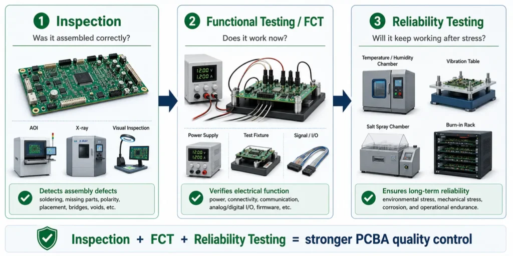
Before choosing reliability tests, it helps to separate three different layers of PCBA quality assurance:
- Inspection
- Electrical and functional testing
- Reliability validation
They work together, but they do not prove the same thing.
What AOI, X-Ray, ICT, and FCT Can Confirm
Standard PCB assembly quality control often includes multiple inspection and test steps.
AOI checks visible assembly conditions such as missing parts, wrong orientation, polarity errors, solder bridges, tombstoning, skew, insufficient solder, excess solder, and some solder joint appearance issues.
X-ray inspection is useful for hidden solder joints, especially BGA, QFN, LGA, bottom-terminated components, and areas where solder cannot be inspected visually.
ICT or flying probe testing can identify electrical faults such as opens, shorts, incorrect values, wrong component orientation, or net-level faults, depending on test access and fixture design.
FCT powers the board and verifies whether the PCBA performs the intended function under defined test conditions. This may include input/output signals, communication, sensors, relays, displays, firmware operation, or load behavior.
Together, these methods help confirm that the board was assembled correctly and works at the time of factory test.
For a deeper comparison, see PCBAgroup’s guide: AOI vs ICT vs FCT in PCBA Testing.
What Reliability Testing Is Designed to Reveal
Reliability testing asks a different question.
It does not only ask, “Does the PCBA work now?” It asks, “Will this PCBA continue working after realistic or accelerated stress?”
Reliability testing can help reveal failure modes such as:
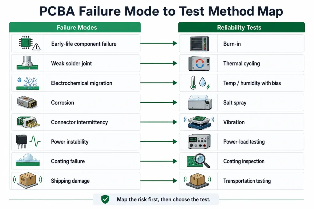
| Failure mode | Typical cause | Relevant test or review |
|---|---|---|
| Early-life component failure | Marginal component, weak semiconductor, capacitor leakage, thermal stress | Burn-in, powered load testing, thermal monitoring |
| Weak solder joint | Poor wetting, insufficient solder, mechanical stress, thermal mismatch | Thermal cycling, vibration, X-ray for hidden joints, cross-section if needed |
| Electrochemical migration | Ionic residue, humidity, voltage bias, inadequate spacing | Cleanliness review, temperature/humidity with bias, SIR-style evaluation when required |
| Corrosion | Salt mist, moisture, flux residue, exposed metal, poor plating, coating gaps | Salt spray, humidity testing, coating inspection, connector review |
| Connector intermittency | Vibration, fretting, insufficient retention, cable stress | Vibration testing, mating/unmating review, connector-specific test plan |
| Power instability | Load transients, thermal rise, poor derating, firmware state transitions | Power-load testing, burn-in, current logging, thermal imaging |
| Coating failure | Poor cleaning, bubbles, voids, pinholes, masking errors, incompatible material | Coating inspection, humidity validation, functional test before and after coating |
| Shipping damage | Packaging weakness, unsupported heavy parts, board flex, shock | Simulated transportation testing, packaging validation, mechanical review |
These issues often require time, stress, environment, or load to appear. A short functional test may not reveal them.
Why Passing FCT Does Not Always Mean Field Reliability
FCT is a powerful tool, but it is not a lifetime test.
A board may boot, communicate, switch outputs, and pass all functional limits at room temperature. That does not prove it will survive a humid outdoor enclosure, a long burn-in under load, repeated thermal expansion and contraction, or shipping vibration.
Examples:
- A weak solder joint may pass initial testing but open intermittently after vibration.
- Flux residue may be harmless on a dry bench but create leakage under humidity and voltage bias.
- A connector may pass FCT but loosen after transport or repeated mating.
- A battery-powered PCBA may pass a quick power-on test but fail under long sleep/wake cycles.
- A coated board may pass before coating but fail after coating due to masking, curing, trapped contamination, or inaccessible test points.
- A high-current connector may pass briefly but overheat after sustained load.
“Works at shipment” and “survives in the field” are related, but they are not the same promise.
When Standard PCBA Quality Control Is Enough
Not every PCB assembly needs complex environmental reliability testing. A good supplier should help you avoid unnecessary testing, not simply add more test items.
Low-Risk Boards May Not Need Extra Environmental Testing
Standard PCBA quality control may be enough when the product has low reliability risk.
Examples include:
- Indoor products used in stable temperature and humidity
- Simple low-current control boards
- Low-voltage products without harsh environment exposure
- Short-life accessories where field replacement is easy
- Engineering prototypes built mainly for functional evaluation
- Boards without coating, potting, condensation, salt, vibration, or high-current requirements
For these projects, process review, IQC, SPI, AOI, X-ray when required, visual inspection, basic electrical testing, and FCT may provide sufficient production confidence.
Extra Testing Can Add Cost Without Improving the Decision
More testing is not automatically better.
If the test condition does not match the real product risk, the result may not improve the decision. For example, salt spray testing may not add much value for a sealed indoor product with no coastal, outdoor, or corrosive exposure. A long burn-in may not be cost-effective for a simple low-risk board with low field failure cost.
Reliability testing should reduce uncertainty. It should not be added only because it sounds impressive.
The Better Question Is "What Risk Are We Reducing?"
Before adding a reliability test, ask:
- What field failure are we trying to prevent?
- How likely is that failure mode?
- How expensive would the failure be?
- Can this test realistically reveal the risk?
- Is the test condition connected to the actual use environment?
- Should this be tested during design validation, pilot run, or every production batch?
This keeps the test plan practical and defensible.
When Extra PCBA Reliability Testing Becomes Necessary
Extra reliability testing becomes important when the product environment, field failure cost, customer requirement, or design uncertainty creates meaningful risk.
Harsh Operating Environments Increase Reliability Risk
Reliability testing should be reviewed when the product will face:
- High temperature
- Low temperature
- Temperature cycling
- High humidity
- Condensation
- Dust
- Salt mist
- Chemical exposure
- Outdoor installation
- Repeated vibration
- Mechanical shock
- Long operating hours
- High current or high power
These conditions can expose weaknesses that a normal factory functional test may miss.
For example:
- Outdoor IoT devices may need humidity, condensation, coating, cleaning, and enclosure review.
- Industrial controllers may need burn-in, power-load testing, vibration review, and traceability.
- Battery-powered products may need charge/discharge, protection, standby current, and thermal validation.
- Coastal or marine-adjacent products may need corrosion-risk review and possible salt mist testing.
High Field Failure Cost Changes the Test Strategy
Field failure cost is not only the cost of one PCBA.
It may include:
- Customer downtime
- Technician travel
- Product returns
- Rework labor
- Replacement shipping
- Contract penalties
- Brand damage
- Lost repeat orders
If a failed PCBA is difficult to access after installation, extra reliability validation becomes more valuable.
This is common in industrial equipment, outdoor infrastructure, medical-adjacent products, energy systems, transportation electronics, and products installed far from the manufacturer.
New Design, New Supplier, or New Process Means New Risk
Reliability testing is also useful when something changes.
Examples include:
- First prototype of a new product
- First pilot run before mass production
- New PCBA supplier
- New PCB material or surface finish
- New approved alternate component
- New solder paste or flux chemistry
- New low-temperature soldering process
- New selective soldering or wave soldering requirement
- New conformal coating or potting process
- New firmware or power profile
- New enclosure or packaging method
Each change can introduce new failure modes. A focused validation plan can reduce risk before large batches are released.
Burn-In Testing for PCBA
Burn-in testing is one of the most common reliability-related requests in PCB assembly. It is also one of the easiest to misunderstand.
What Is PCBA Burn-In Testing?
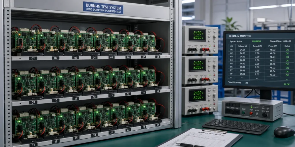
PCBA burn-in testing means operating the assembled board under defined powered conditions for a defined period of time. The purpose is to screen early-life failures before shipment.
The idea is often explained with the “bathtub curve” of electronic product failure. Many products have a higher early failure rate at the beginning of life, followed by a more stable useful-life period, and finally a wear-out period. Burn-in is intended to expose weak components, marginal solder joints, unstable power circuits, or process-related issues before the customer receives the product.
Burn-in may be performed at room temperature or elevated temperature. It may use real loads, simulated loads, communication cycles, relay switching, charging/discharging, firmware test modes, or periodic functional checks.
What Problems Burn-In Can Detect
Burn-in can help reveal:
- Weak solder joints that become intermittent when warmed
- Marginal ICs or passive components
- Capacitor leakage or abnormal current drift
- Power supply instability
- Voltage ripple or regulator thermal stress
- MOSFET, relay, or driver failure under repeated load
- Firmware instability during long operation
- Communication dropouts after extended runtime
- Thermal shutdown or over-temperature behavior
- Early-life failures that do not appear in a short FCT
Burn-in is especially useful for products that operate continuously or where early field failure would be expensive.
What Burn-In Cannot Prove
Burn-in is not a complete lifetime guarantee.
It does not automatically prove:
- Full product life
- Resistance to humidity
- Resistance to corrosion
- Resistance to vibration
- Correct enclosure design
- Correct conformal coating coverage
- Compliance with every customer reliability standard
Burn-in is one part of the reliability plan. It should be combined with inspection, functional testing, process control, environmental validation, and documentation when product risk requires it.
Common Burn-In Conditions Buyers Should Define
Before asking for a PCB burn-in test, define the test conditions.
| Burn-in item | What to specify |
|---|---|
| Power input | Nominal voltage, voltage range, current limit, power supply type |
| Load condition | No-load, partial load, full load, simulated load, real product load |
| Runtime | Several hours to several days depending on product risk and customer requirements |
| Temperature | Room temperature or elevated temperature condition |
| Functional mode | Firmware mode, communication cycle, switching cycle, charge/discharge state |
| Monitoring | Current logging, voltage logging, temperature monitoring, manual checks, automatic alerts |
| Pass/fail criteria | Reset, communication loss, abnormal current, overheating, output drift, functional failure |
| Sample plan | 100 percent burn-in, sample-based burn-in, prototype validation, or pilot-run validation |
Avoid vague instructions such as “burn-in required.” They leave too much room for assumptions.
When Burn-In Is Worth the Added Cost
Burn-in is more likely to be worthwhile when:
- The product runs continuously in the field.
- Field repair is expensive or difficult.
- The assembly includes high-current, power, relay, or thermal risk.
- Early-life failure would damage customer trust.
- The design is new or has not yet been validated.
- The project is moving from prototype to pilot run or mass production.
- The customer requires powered screening before shipment.
For low-risk indoor products, short FCT and normal quality control may be enough. For industrial, outdoor, power, communication, battery, and long-life products, burn-in can be a practical way to reduce early failure risk.
Temperature and Humidity Testing for PCB Assemblies
Temperature and humidity are among the most common causes of hidden PCBA reliability problems.
Why Moisture and Temperature Stress Matter for PCBAs
Moisture and temperature stress can affect PCB assemblies in several ways:
- Condensation forms on the board surface during temperature change.
- Flux residues or ionic contamination absorb moisture.
- Insulation resistance decreases.
- Leakage current increases.
- Electrochemical migration creates conductive dendrites.
- Exposed metal, terminals, and solder joints corrode.
- Sensors drift.
- Connectors oxidize or become unstable.
- Coating defects such as bubbles, voids, pinholes, or poor adhesion become more serious.
- Different materials expand and contract at different rates, stressing solder joints.
These risks become more important for outdoor, industrial, agricultural, HVAC, marine-adjacent, and humid-environment products.
What Temperature/Humidity Testing Can Reveal
Temperature and humidity testing can help reveal:
- Residue-related leakage
- Ionic contamination risk
- Weak cleaning process control
- Moisture-sensitive component issues
- Connector or exposed metal corrosion
- Inadequate spacing for high-voltage or high-impedance nets
- Coating coverage problems
- Sensor instability under environmental stress
- Battery or low-power circuit current drift
Some customers request damp heat, thermal cycling, or “85/85” style validation, such as exposure around 85 degrees C and 85 percent relative humidity. These conditions should not be copied blindly. They should be selected based on product requirements, materials, components, customer standards, and expected use environment.
Temperature Cycling vs Temperature/Humidity Testing
Temperature cycling and temperature/humidity testing are related, but they reveal different risks.
Temperature cycling focuses on repeated expansion and contraction. It is useful for identifying solder joint fatigue, package stress, BGA or QFN joint risk, material mismatch, and intermittent failures that occur when the board moves between hot and cold conditions.
Temperature/humidity testing adds moisture. It is useful for identifying leakage, corrosion, electrochemical migration, coating defects, moisture-sensitive materials, and residue-related issues.
A product can pass one test and fail the other because the failure mechanisms are different.
How This Connects to Cleaning and Conformal Coating
Temperature/humidity testing should be connected to PCB assembly cleaning, ionic contamination control, conformal coating, and enclosure design.
If flux residue or ionic contamination remains on the board, humidity can activate leakage paths or electrochemical migration that were invisible during a dry factory test. If conformal coating is applied over contamination or moisture, the coating may trap the problem instead of solving it.
Important points:
- Cleaning quality affects humidity performance.
- No-clean flux does not mean no residue.
- Coating does not replace correct cleaning, spacing, soldering, or inspection.
- Test pads, connectors, switches, and keep-out areas must be planned before coating.
- Functional testing may be needed before and after coating.
Related PCBAgroup guides:
What Buyers Should Provide for Temperature/Humidity Testing
If your project needs environmental validation, provide:
- Operating temperature range
- Storage temperature range
- Humidity condition
- Whether condensation is expected
- Whether the test is powered or unpowered
- Product enclosure information
- Coating or potting requirement
- Cleaning requirement
- Test duration
- Sample quantity
- Functional check before, during, and after exposure
- Acceptance criteria
- Required report format
Without these details, the supplier can only provide a general recommendation.
Vibration and Simulated Transportation Testing
Vibration testing is important when mechanical stress can damage the PCBA, loosen connections, crack solder joints, or create intermittent contact.
Why PCBAs Fail During Shipping or Mechanical Operation
Vibration can come from transportation or from actual product use.
Shipping stress may come from truck transport, air transport, sea freight, warehouse handling, packaging compression, or repeated movement. Operating vibration may come from motors, compressors, vehicles, pumps, industrial machinery, or handheld equipment.
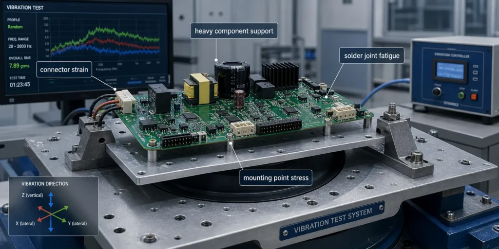
Vibration can cause:
- Connector loosening
- Intermittent contact
- Cracked solder joints
- Lead fatigue in large through-hole components
- Board flex near mounting points
- Wire harness strain
- Heatsink movement
- Relay instability
- Broken plastic clips or standoffs
- Damage to packaging or product enclosure
These failures may not appear during static functional testing.
Components Most at Risk During Vibration
The highest-risk components usually have mass, height, leverage, or repeated mechanical stress.
| Component or area | Typical vibration risk |
|---|---|
| Connectors | Intermittent contact, cracked solder joints, cable strain, fretting corrosion |
| Transformers and inductors | Solder joint fatigue, board flex, need for staking or mechanical support |
| Electrolytic capacitors | Lead stress, adhesive failure, movement due to height and mass |
| Relays | Internal mechanical instability, solder joint stress, contact issues |
| Heatsinks | Screw loosening, board stress, component movement |
| Large through-hole parts | Lead fatigue, solder fillet cracking, mechanical leverage |
| Wire harness interfaces | Pulling, fretting, increased contact resistance |
| Board mounting holes | Stress concentration, board cracking, enclosure mismatch |
For these products, vibration risk should be reviewed during DFM, not after production.
Simulated Transportation Testing vs Operating Vibration
Simulated transportation testing and operating vibration testing are not the same.
Simulated transportation testing checks whether the packaged product or shipped PCBA can survive shipping and handling stress.
Operating vibration testing checks whether the product can survive vibration while installed and powered in the real application.
For example:
- A bulk-shipped PCBA may need packaging validation.
- A control board installed near a motor may need operating vibration review.
- A vehicle-mounted product may need customer-defined vibration profiles.
- A handheld product may need mechanical shock or drop-related review at the product level.
The test profile should match the real risk.
What Buyers Should Tell the Supplier
Before requesting vibration or transportation testing, provide:
- Product application
- Shipping method
- Packaging method
- Whether the PCBA ships alone or inside a finished product
- Installation orientation
- Mounting hole locations
- Mechanical support points
- Heavy component locations
- Connector and cable information
- Whether staking, adhesive, bracket, or support is required
- Customer vibration profile or standard if available
- Functional check required after test
- Acceptance criteria
If no vibration profile exists, the supplier can help review mechanical risk, but the final product-level requirement should come from the product owner or customer specification.
Salt Spray Testing for PCB Assembly
Salt spray testing is useful for certain products, but it should not be treated as a generic requirement for every PCBA.
When Salt Spray Testing Is Relevant
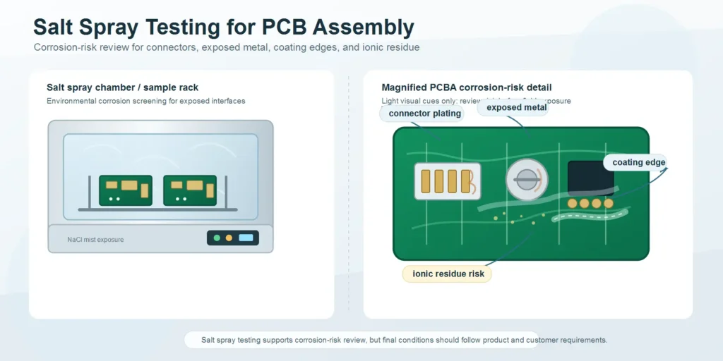
Salt spray or salt mist testing should be considered when the product may face corrosion risk.
Examples include:
- Outdoor electronics
- Coastal or marine-adjacent equipment
- Transportation equipment
- Industrial equipment in corrosive environments
- Products with exposed connectors or terminals
- Assemblies installed near salt, chemicals, moisture, or corrosive gases
For sealed indoor electronics, salt spray testing may not add meaningful value unless the customer requires it.
What Salt Spray Testing Can Reveal
Salt spray testing can help evaluate corrosion resistance of metallic materials, exposed metal, connectors, soldered interfaces, screws, surface finishes, coatings, and protective treatments.
It may reveal:
- Connector corrosion
- Exposed metal corrosion
- Poor coating coverage
- Weak surface protection
- Residue-related corrosion risk
- Discontinuities such as pores or defects in protective coatings
- Corrosion around soldered or mechanical interfaces
For PCBA projects, salt spray testing should be connected to connector choice, coating, cleaning, enclosure design, exposed metal protection, and surface finish selection.
What Salt Spray Testing Cannot Prove
Salt spray testing is not a perfect lifetime prediction.
It does not automatically prove:
- Exact years of field life
- Resistance to every real-world environment
- Correct enclosure sealing
- Resistance to humidity without salt
- Resistance to vibration or thermal cycling
- Complete protection against electrochemical migration
The result should be interpreted as corrosion-resistance screening or customer-defined environmental validation, not a universal lifetime guarantee.
Design and Material Factors That Affect Corrosion Risk
Corrosion risk depends on the full product design, not just the test chamber.
Important factors include:
- PCB surface finish
- Connector plating
- Exposed copper or metal
- Solder mask coverage
- Conformal coating material and coverage
- Cleaning and ionic residue control
- Enclosure sealing and ventilation
- Drainage and condensation path
- Cable entry points
- Galvanic interaction between metals
- Operating voltage and creepage/clearance
- Storage and packaging before shipment
Salt spray testing should be discussed early if the product will operate in coastal, outdoor, transportation, or corrosive industrial environments.
Battery, Power-Load, and High-Current PCBA Testing
Battery-powered and high-current PCBAs often need more than a simple power-on test.
Why Battery-Powered PCBAs Need Extra Validation
Battery-powered assemblies can fail in ways that a short FCT may miss.
Examples include:
- Abnormal standby current
- Fast battery drain
- Charging instability
- Protection circuit misbehavior
- Overcurrent protection delay
- Over-temperature behavior
- Voltage drop under load
- MOSFET overheating
- Connector temperature rise
- Firmware sleep/wake failure
- Reset during load transition
For battery-powered products, testing should include realistic operating states, not only a quick boot test.
What to Check Under Load Conditions
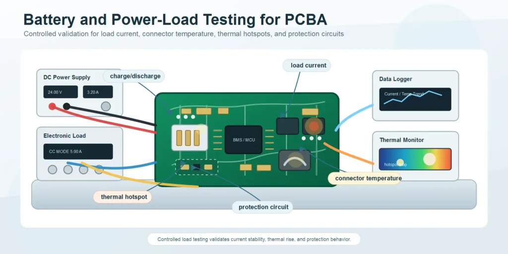
Power-load testing may include:
- Input voltage range
- Output voltage stability
- Current draw under each operating mode
- Peak current and surge behavior
- Load switching behavior
- Connector temperature rise
- Charging and discharging behavior
- Protection circuit response
- Thermal performance around regulators, MOSFETs, inductors, resistors, and connectors
- Functional behavior under full-load or simulated-load conditions
For high-current boards, thermal imaging or thermocouple monitoring can help identify hot spots. However, the exact method should match the product and customer requirement.
Charge/Discharge and Protection Circuit Validation
Battery-related products may require validation of:
- Charging voltage and current
- Discharging behavior
- Overcharge protection
- Over-discharge protection
- Overcurrent protection
- Short-circuit protection
- Temperature protection
- Recovery behavior after fault
- Cycle-related current drift or parameter shift
For final products that include battery packs, cells, or shipping requirements, additional product-level standards or certifications may apply. These should be handled as customer or certification requirements, not assumed from a generic PCBA test plan.
Safety and Documentation Expectations
Battery and high-current testing should be documented carefully.
Useful records may include:
- Firmware version
- BOM version
- PCB revision
- Test voltage and current
- Load condition
- Test duration
- Temperature observations
- Pass/fail criteria
- Failure log
- Serial number or batch traceability
- Photos or test report when required
If safety-related abnormalities occur, the test should stop and the root cause should be reviewed before shipment or retest.
How Reliability Testing Affects Cost and Lead Time
Reliability testing improves confidence, but it also affects quotation, capacity, fixture planning, and schedule.
Test Duration, Sample Quantity, and Fixture Needs Affect Cost
Reliability testing cost depends on:
- Test duration
- Number of samples
- Whether testing is 100 percent or sample-based
- Fixture or jig requirement
- Power supply and load equipment
- Firmware and software setup
- Monitoring and data logging
- Engineering review time
- Report format
- Retest requirement after failure
A 10-minute FCT and a 24-hour burn-in test have very different production impact. A sample-based temperature/humidity validation and a 100 percent environmental test also require different planning.
Typical Timing Ranges Should Be Treated as Planning Examples
Some test durations are often discussed as ranges, but they should not be treated as universal rules.
Examples:
- Burn-in may range from several hours to several days, depending on product risk and customer requirements.
- Temperature/humidity exposure may require days or longer when used for validation.
- Vibration or simulated transportation testing may require fixture setup, packaging preparation, test execution, and post-test inspection.
- Salt mist testing may be specified for a defined number of hours by a customer or standard.
- Battery charge/discharge validation may take longer than expected because the cycle time is tied to real electrical behavior.
The test time itself is only one part of lead time. Preparation, fixture building, firmware loading, sample installation, monitoring, post-test inspection, reporting, and failure analysis can add additional time.
Reliability Testing Can Change the Production Sequence
Reliability requirements can affect the manufacturing flow.
Examples:
- Programming may need to happen before burn-in.
- FCT may be needed before and after burn-in.
- Cleaning and drying may be needed before coating.
- Coating may need curing time before final test.
- Test pads may become inaccessible after coating.
- Battery products may need charge/discharge timing.
- Failed units may need failure analysis before shipment approval.
If these steps are not included during RFQ review, the quotation and lead time may change after production starts.
Prototype vs Pilot Run vs Mass Production Testing
| Stage | Practical reliability focus |
|---|---|
| Prototype | Identify design risk, component risk, thermal risk, firmware risk, and test access risk |
| Pilot run | Validate process repeatability, fixtures, packaging, documentation, and sample reliability |
| Mass production | Use defined inspection, FCT, sampling, burn-in, traceability, and process controls to maintain repeatability |
For mass production, not every environmental test needs to be performed on every unit. Some tests are best used for validation, while production relies on process control, inspection, sample testing, traceability, and defined acceptance rules.
How to Avoid Over-Testing and Under-Testing
To avoid under-testing, define the real field environment and failure cost.
To avoid over-testing, define which test result will change your decision.
If a test result will not affect design approval, supplier approval, batch release, customer acceptance, or corrective action, the test may need to be reconsidered.
What to Include in Your PCBA Reliability Testing RFQ
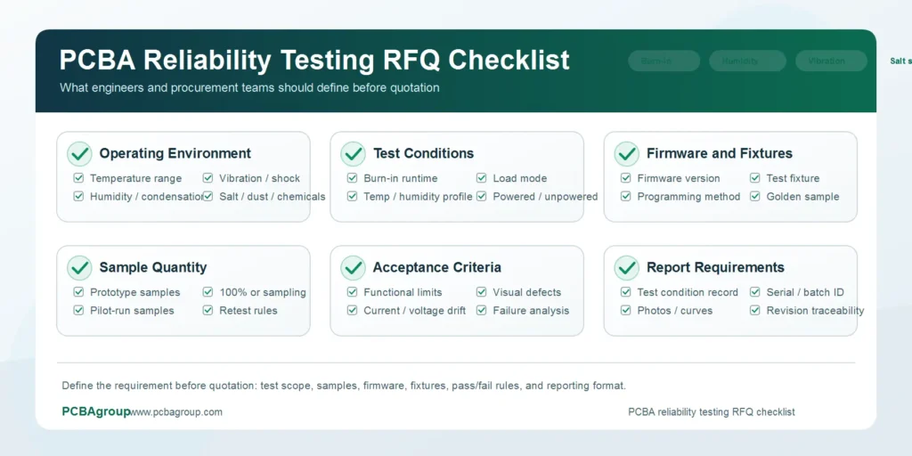
The RFQ is where many reliability problems begin. If reliability requirements are not defined early, the supplier may quote without the correct fixture, labor, test time, equipment, reporting, or process sequence.
Operating Conditions
Include the real operating conditions whenever possible.
Useful information includes:
- Indoor or outdoor use
- Temperature range
- Humidity range
- Whether condensation may occur
- Dust, salt, or chemical exposure
- Vibration or shock exposure
- Input voltage and current
- Peak current or surge current
- Load type
- Expected operating hours
- Expected service life
- Enclosure information
- Cooling method
This information helps the supplier recommend an appropriate test plan instead of guessing.
Test Standards or Customer-Specific Requirements
If your customer requires a specific standard or internal test method, include it in the RFQ.
Examples that may be referenced in electronics reliability discussions include:
- IPC-A-610 for electronic assembly acceptability
- J-STD-001 for soldered electrical and electronic assemblies
- IPC-TM-650 test methods for selected chemical, mechanical, electrical, and environmental evaluations
- IEC 60068 family methods for environmental testing
- Customer-specific automotive, industrial, medical, telecom, or product-level requirements
Do not simply write “test according to standard.” Specify the test method, condition, duration, sample quantity, acceptance criteria, and report requirement.
Acceptance Criteria and Test Reports
Every reliability test should have a pass/fail rule.
Examples include:
- No functional failure after test
- No abnormal current increase
- No communication failure
- No visible corrosion beyond agreed limit
- No connector loosening
- No coating crack, bubble, void, or delamination beyond agreed limit
- No solder joint crack under the agreed inspection method
- No reset or abnormal event during burn-in
- Test report required with serial number, test condition, time, result, and photos
- Failure analysis required if a sample fails
If acceptance criteria are not defined, the supplier and customer may interpret the result differently.
Firmware, Fixtures, and Golden Samples
Many reliability tests require customer input.
Provide:
- Firmware file and version
- Programming instructions
- Test procedure
- Communication protocol or test command
- Load condition
- Golden sample if needed
- Test fixture or fixture design requirement
- Cable and connector requirements
- Software tool or driver if needed
- Test limits
For complex products, the test plan should be reviewed before production so the supplier can prepare fixtures and avoid delays.
Example RFQ Wording for Reliability Testing
For an industrial control product:
This PCBA will be used in an industrial control product installed in a humid indoor environment. Please review reliability risk before quotation. We need SMT assembly, through-hole assembly, AOI, X-ray for BGA/QFN if applicable, programming, FCT, and a recommended burn-in or environmental test plan. Please quote test fixture cost separately and confirm what information you need from us for firmware, load condition, pass/fail criteria, and test reports.
For an outdoor IoT product:
This PCBA will be used in an outdoor IoT device. Please review cleaning, conformal coating, temperature/humidity exposure, connector corrosion risk, and final functional testing before quotation. The product may face humidity and condensation. Please recommend whether salt spray testing is necessary based on the enclosure and application.
For a battery-powered product:
This PCBA includes battery charging and protection circuits. Please review charge/discharge test requirements, standby current, load condition, connector temperature rise, firmware test mode, and protection-circuit validation before quotation. We will provide firmware, test commands, load conditions, and acceptance criteria.
Clear RFQ wording helps the manufacturer quote the real project instead of a simplified version of it.
Reference Standards and How to Use Them Correctly
Standards are useful, but they should be applied carefully. A standard name alone does not define a complete reliability test plan.
IPC-A-610 and J-STD-001 Are Not Environmental Qualification Plans
IPC-A-610 and J-STD-001 are widely used in electronics assembly. IPC has described IPC-A-610 as a post-assembly acceptability standard and J-STD-001 as a standard for soldering process and materials requirements.
These standards are important for assembly acceptance and soldering quality, but they do not automatically define your burn-in, humidity, vibration, or salt spray test conditions.
Use them as part of quality control, not as a substitute for product-specific reliability validation.
IPC-TM-650 Contains Useful Test Methods, But Method Selection Matters
IPC-TM-650 includes many test methods across reporting, visual, dimensional, chemical, mechanical, electrical, environmental, and connector-related categories. For PCBA reliability discussions, buyers may encounter methods related to ionizable surface contaminants, electrochemical migration, insulation resistance, dendritic growth, conformal coating, connectors, or environmental testing.
The key is method selection. Do not ask for an IPC-TM-650 test unless you know which method, sample type, condition, and acceptance criteria apply to your product.
IEC 60068 Is a Family of Environmental Test Methods
IEC 60068 is often referenced for environmental testing. It includes many different test methods for environmental stresses. For example, IEC 60068-2-11 covers salt mist testing for assessing corrosion resistance of electrotechnical products, components, equipment, and materials in a salt mist environment.
That does not mean every PCBA needs IEC 60068 testing. It means the relevant method can be used when the product requirement calls for it.
Customer Requirements Should Control the Final Test Plan
For automotive-related, medical-adjacent, battery, transportation, industrial, telecom, or safety-related products, customer-specific requirements may be more important than generic PCBA guidance.
If your customer or certification path defines test conditions, sample quantity, temperature profile, vibration profile, acceptance criteria, or report format, provide those requirements during RFQ review.
How PCBAgroup Supports Reliability Validation
Published PCBAgroup Quality-Control Capabilities
PCBAgroup’s published quality-control page describes MES traceability, process review, IQC, SPI solder paste inspection, online AOI, first sample testing, offline AOI, X-ray inspection, manual QC inspection, and an environmental and performance testing lab.
The same page lists support for:
- Constant temperature and humidity testing
- Simulated transportation vibration testing
- Salt spray testing
- Battery testing
- BGA rework capability
- MES-driven process history and inspection records
These published capabilities support reliability-related validation, troubleshooting, and corrective action when matched to the product requirement.
Engineering Review Before Testing
A useful PCBA test plan starts before the first board is built.
PCBAgroup can review application requirements, BOM, Gerber files, centroid data, assembly drawings, coating requirements, cleaning requirements, test requirements, and production stage to identify risks early.
Many reliability failures are connected to upstream decisions:
- Component selection
- PCB material and surface finish
- Pad and footprint design
- Thermal layout
- Connector choice
- Cleaning and coating compatibility
- Test point access
- Fixture planning
- Packaging method
- Revision control
Testing is more useful when it is connected to DFM, sourcing, process control, and customer requirements.
Documentation for Overseas Buyers
For customers in the United States, Europe, Australia, and other export markets, documentation is often as important as the test itself.
Useful documentation may include:
- Quotation assumptions
- DFM or risk review notes
- Test procedure
- Fixture requirement
- Burn-in condition
- Functional test result
- Batch traceability
- Inspection record
- Environmental test report
- Failure analysis if defects occur
- Revision control record
Clear documentation helps engineering teams approve the build and helps procurement teams compare suppliers fairly.
Final Checklist Before You Approve a PCBA Reliability Test Plan
Buyer Checklist
Use this checklist before sending or approving an RFQ:
- Product application is clearly described.
- Operating environment is defined.
- Temperature and humidity range are provided.
- Condensation, salt, dust, vibration, or chemical exposure is identified.
- Expected service life is stated.
- Power input and load condition are defined.
- Firmware version and programming method are controlled.
- Functional test procedure is provided.
- Burn-in condition is defined if required.
- Environmental test condition is defined if required.
- Sample quantity is agreed.
- Test duration is agreed.
- Pass/fail criteria are written.
- Report format is agreed.
- Coating, cleaning, potting, or special process requirements are included.
- Packaging and shipping risk are reviewed.
- Revision control is clear across BOM, Gerber, centroid, drawings, firmware, and test files.
Supplier Questions to Ask
Before approving production, ask your PCBA supplier:
- Which tests are performed on every unit?
- Which tests are sample-based?
- Which tests are validation-only during prototype or pilot run?
- What defects can each test detect?
- What defects can still escape?
- What information do you need from us for FCT or burn-in?
- Is a test fixture required?
- How will test results be recorded?
- What happens if a unit fails during burn-in or environmental testing?
- Can the failed unit be traced to BOM version, PCB revision, firmware version, and production batch?
- Does the test plan affect lead time?
These questions turn “quality control” from a general promise into a controlled manufacturing process.
FAQ
Is burn-in testing required for every PCBA?
No. Burn-in testing is not required for every PCBA. It is most useful when the product runs continuously, has high field failure cost, includes power or thermal risk, or must screen early-life failures before shipment. For simple low-risk indoor products, standard inspection and functional testing may be enough.
Is FCT enough for reliable PCB assembly?
FCT is important, but it may not be enough for every product. FCT confirms that the board performs defined functions at the time of testing. It does not always prove long-term reliability under humidity, vibration, heat, salt mist, or extended powered operation. Higher-risk products may need additional reliability testing.
How long should PCBA burn-in testing last?
There is no universal burn-in duration for every PCBA. The correct duration depends on product risk, customer requirements, load condition, operating environment, cost target, and production stage. Some projects use a short powered run. Others require longer burn-in under defined temperature and load conditions.
Do I need temperature and humidity testing if my board has conformal coating?
Maybe. Conformal coating can reduce environmental risk, but it does not replace good cleaning control, correct coating coverage, proper spacing, good soldering, and final functional validation. If the product will face humidity, condensation, outdoor use, or long service life, temperature and humidity testing may still be useful.
What is the difference between temperature cycling and temperature/humidity testing?
Temperature cycling mainly stresses solder joints, packages, materials, and mechanical interfaces through repeated expansion and contraction. Temperature/humidity testing adds moisture stress and is more relevant to leakage current, corrosion, insulation resistance, electrochemical migration, coating defects, and residue-related risk.
When is salt spray testing needed for PCB assembly?
Salt spray testing is most relevant for products exposed to coastal, outdoor, transportation, industrial, or corrosive environments. It may not be necessary for sealed indoor products unless a customer standard requires it. The test should be connected to connector selection, coating, cleaning, enclosure design, and material choices.
What should I send to a PCBA manufacturer for reliability testing?
Send Gerber files, BOM, centroid file, assembly drawing, schematic if available, firmware, test procedure, expected operating environment, power and load conditions, reliability requirements, coating or cleaning needs, sample quantity, test duration, acceptance criteria, and report requirements.
Final Thoughts
PCBA reliability testing should be practical, not excessive.
The purpose is not to request every possible test. The purpose is to understand the product risk and choose the tests that give meaningful confidence before shipment.
For low-risk indoor PCB assemblies, standard quality control and functional testing may be sufficient. For industrial, outdoor, battery-powered, high-current, medical-adjacent, automotive-related, or long-life products, extra reliability validation may be the difference between a smooth launch and expensive field failures.
The best time to discuss reliability testing is before quotation, not after production starts. When the supplier understands the application environment, product risk, test conditions, firmware, load requirements, and acceptance criteria early, the quotation becomes more accurate and the production plan becomes easier to control.
If your PCB assembly project needs burn-in testing, temperature/humidity testing, vibration testing, salt spray testing, battery testing, functional test planning, or reliability-focused process review, send your Gerber files, BOM, centroid file, assembly drawing, test requirements, and application environment to PCBAgroup. Our Shenzhen engineering and manufacturing team can help review the right inspection and reliability test strategy before prototype, pilot run, or mass production.
Need help defining a PCBA reliability test plan for your next build?
Contact PCBAgroup with your Gerber files, BOM, centroid file, assembly drawing, firmware/test requirements, and product operating environment. We can review your assembly, inspection, testing, and reliability risks before production starts.